FIRST Robotics Competition Blog

Community Browser
cancel
Showing results for 
Search instead for 
Did you mean: 
robo_Jeff
6622 Views
0 Comments

Did you know that there are a bunch of built-in FRC examples right in LabVIEW? There are!

Just click on the Help drop-down menu and choose Find Examples. Shablam!  LabVIEW Example Finder!  You'll see an FRC Robotics folder and a roboRIO folder inside it. There, you'll find examples for everything from CAN and Pneumatics to Joystick, Sensors, and Vision.

These examples are ready to run!  You can also customize them, change them, and use them however you want. You can combine them, copy/paste parts of them into other VIs or into your robot project, or just run them independently. The world is your VI!

Have fun!

muffin.vi
5392 Views
0 Comments

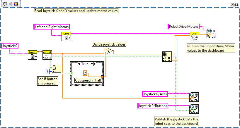
Sometimes during the competition, it would be nice if the sensitivity of the joystick could be lowered temporarily to allow you to maneuver more precisely. The code snippet below does exactly that. If you press button #7 on your gamepad (this is the right trigger on my gamepad), it halves the sensitivity of the joystick. That way, you can drop the sensitivity mid-match by simply holding down the right button.

Replace the joystick and motor code in Telop.vi with the snippet below.

JoystickSensitivity.png

The code is quite simple: the Joystick Get Values function outputs both an array of joystick data and an array of boolean button data. The index array function is used to get the boolean value of the specified button, in this case, button #7. That value is fed into a case structure. If the button is pressed, the case structure gives a value of 2. If it is not pressed, it gives a value of 1. The value of the joystick position is then divided by the output. This way, when button #7 is pressed, every joystick value is divided by two, dropping the sensitivity. If button #7 is not pressed, the joystick sensitivity is unchanged and the robot moves at full speed.

Kelly_B
5136 Views
0 Comments

This example illustrates how to control a servo on your robot using an input - in this case, a potentiometer.  The potentiometer can be replaced with a joystick input, LabVIEW Front Panel input, or anything else that can be made to output a value between 0 and 1.

This VI Snippet uses a running average to output the mean of the last 5 potentiometer inputs to the servo. This helps to keep the servo's movement smooth.  Each new potentiometer value is stored in an array in the order it is read.  Once the array is full, the values are written over the existing values starting from the beginning.  The size of the array can be changed to include different quantities of values in the average.

Potentiometer Servo.png

Shane-C
6452 Views
0 Comments

One of the first challenges every programmer faces when beginning with a new programming environment is learning how to troubleshoot their code.  There are several simple techniques that can help save you a great deal of time when trying to find the source of a problem with your code.

  1. Probes
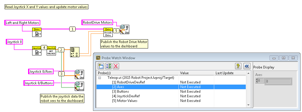
    Probes tell you the current state of the data on the wire they are attached to in your program.  In the screenshot below you’ll notice small numbered icons placed on the wires between subVIs in my code.  To create these probes, right click on a wire and select Probe.  Once the probe is placed, the Probe Watch Window automatically shows up.  As your code is executing the Probe Watch Window will continuously update with new data values each time new data is passed on that wire.  If I suspected an issue may be occurring in my Teleop.vi and had placed the probes as seen below I would be able to tell if I had a hardware connection or refnum naming issue by looking at probes 1 and 4 so see if they populate with values. Probes 2, 3 and 5 would tell me if I was receiving correct data and sending correct values to my motors.

    Probe Snippet.png
  2. Keep Code Organized
    Disorganized code can be very difficult to debug or ask for help with.  The code snippet below has identical functionality to the code above, but it is much more difficult to read.  Some of these functions have wires going backwards, and for others such as the index array function, it is near impossible to tell what is an input and what is an output. You may know what your code is doing today, but in two months it may be very difficult to remember exactly what it's purpose is.  It is easy to resolve issues like this through organization, block diagram comments, and by using the automatic Diagram cleanup tool in LabVIEW.  In the screenshot from item 3 below, the last item that looks like a broom (highlighted in red in the image) is the Block Diagram Cleanup tool. Click it and LabVIEW will attempt to organize your entire block diagram in a logical format, that reads left to right.  The code below will very closely resemble the code above after running this tool. You can also run the cleanup tool on sections of your code by highlighting a section and typing <CTRL>+U.  For more information see this link: http://www.ni.com/tutorial/7386/en
    Keep Code Organized v2.PNG
  3. Highlight Execution
    Click the light-bulb icon in the toolbar of the block diagram (highlighted in red below) to turn on highlight execution mode.  While highlight execution mode is enabled, you will see dots on your block diagram flow along the path the code is currently executing.  If you are unsure what exactly your code is doing, or where to begin troubleshooting, this tool can help you find where your code is getting stuck, having errors, or returning bad data.

    Block Diagram Tool Bar.PNG
  4. These are some of the basic techniques.  There are many more tools LabVIEW provides you to debug your application.  See this link for more information: http://www.ni.com/getting-started/labview-basics/debug

tcap
5951 Views
0 Comments

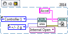
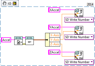
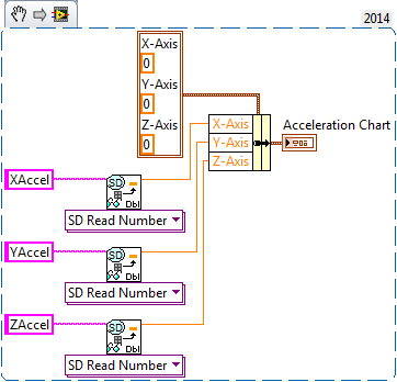
This snippet shows how to read variables from your roboRIO and display them on your custom Dashboard.  It reads the current X, Y, and Z values of the built-in accelerometer and writes them to the SmartDashboard.  The SmartDashboard entries are then read in the PC Dashboard and displayed on a Waveform Chart.

For more information, check out the tutorial from 2014;

https://decibel.ni.com/content/docs/DOC-26296

Begin VI

Place this snippet in the Begin.vi

Begin.png


Teleop VI

Place this snippet in the Teleop.vi

Teleop.png


Finish VI

Place this snippet in Close Refs, save data, etc. frame of the Finish.vi

Finish.png


FRC PC Dashboard VI

Place this snippet within the True case of Loop 1.

DashboardSnippet.png

FRC PC Dashboard VI Front Panel

DashFrontPanel.JPG

Gloorious_Leader
4805 Views
0 Comments

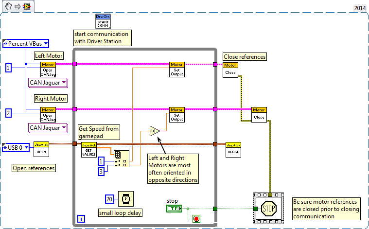
This example shows how tank drive works using a gamepad as a controller. Tank drive allows the driver to control the left and right motors independently of each other. Since each side needs to be controlled separately, one must use two inputs/joysticks to control it. A gamepad is a good choice as it has two joysticks on a single device.

Some gamepads have the ability to disable analog mode, which sets the secondary joystick to read as a button rather than a pair of axes. Be sure that analog mode is enabled when using tank drive.

The code below works by opening a reference to each motor and to the gamepad. In this code the motors are controlled by CAN controllers, but it can be easily modified for another controller type. Because the gamepad has both joysticks on it, only one joystick reference is necessary. The axis position of each stick can be fetched using the JoystickGetValues.vi. The Axes output returns the values of the desired axes (in this case Axis 1 and Axis 3). These values can then be applied to the motors after negating one side since the motor(s) should have an opposite orientation.

This Training Module discusses the basic concepts of motor control. These same concepts are applied in the code below.

Tank Drive Using Gamepad.png

I.B.Hating
4359 Views
0 Comments
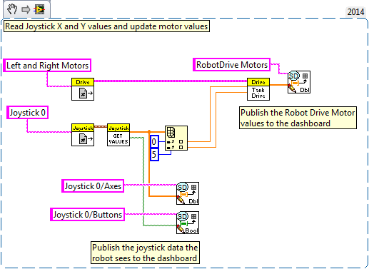
This snippet shows how to modify the FRC roboRIO Project built with the Arcade driving configuration to the Tank driving configuration. The only modifications necessary are to the Teleop VI to make this change. The existing Arcade Drive VI can be directly replaced with the Tank Drive VI found in the same pallet location. Then, the joystick must be configured to control each wheel individually. In the case of the below snippet, a joystick with two thumb-sticks was used where the first thumb-stick maps to row 0 of Joystick 0 and the second thumb-stick maps to row 5 of Joystick 0. Below, the array is indexed by row to get individual data per thumb-stick which is passed into each motor input on the Tank Drive VI.

Teleop VI

Arcade to Tank Drive.png

netsirk
6744 Views
0 Comments

This example explains how to use an encoder to determine the direction and rate of a motor controlled by your roboRIO. Encoder functions can be found in the Encoder subpalette, within the Sensors subpalette of the WPI Robotics Library palette on the block diagram.


These functions work specifically for a quadrature encoder, which contains two rotating disks A and B. Digital pulse outputs from A and B translate into speed, depending on the frequency of pulses, and direction, depending on the which disk’s pulse is detected first.


Connect your quadrature encoder to the DIO pins on the roboRIO such that encoder outputs A and B represent two separate DIO lines. Refer to the diagram shown on the front panel of the MotorwithEncoder.vi example for further direction. (Help > Find Examples > FRC Robotics > roboRIO > Robot and Motor)


How to include in 2015 Robot Project:

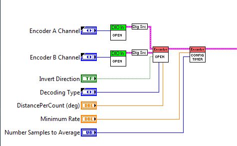
Begin VI


The WPI_EncoderOpen.vi automatically creates an encoder reference from two DIO inputs. (LabVIEW will generate two WPI_DigitalInputOpen.vi’s and convert these to source inputs for this VI). This reference can be passed to WPI_EncoderConfigureTimer.vi, which allows for further configuration of the encoder with inputs that specify the number of pulses to average for rpm calculations, as well as the minimum pulse rate before the encoder is considered stopped.

begin.jpg

Robot Main VI


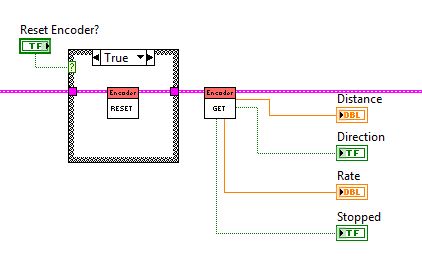
The WPI_EncoderGet.vi is used to return information from the encoder about count, direction, and period of pulses, or if the encoder is stopped. Additionally, the WPI_EncoderReset.vi can be used to reset the encoder to 0 between code executions.

robotmain.jpg

Finish VI


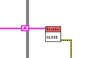
The WPI_EncoderClose.vi is used to close the reference to the encoder.

finish.jpg

Kelly_B
4663 Views
0 Comments

The Producer/Consumer design pattern is a great way to keep two processes in sync when they might run at different rates.  This is especially important when there is data transferred between the loops.  When programming your robot you can use the Producer/Consumer design to save data about motor speed, various voltages, accelerometer data, and a lot more!  This can come in handy as you're testing and fine-tuning your robot.

In this example the Producer loop acquires data from the LabVIEW Front Panel (the "Input Value" and "Scaling Factor" are Front Panel Controls) and adds it to a queue of data to be processed.  The Event Structure is where the data is actually added to the queue.  This part of the code runs when the number in "Input Value" changes (for more on Event Structures, see this blog post).  The Consumer loop then removes each element from the queue, displays it on the Front Panel ("Result Value"), and adds the data to a text file.  Because writing data to a text file is a time consuming activity, the Consumer loop takes longer to run than the Producer loop.


This White Paper talks about the Producer/Consumer pattern in more detail and has some additional example code snippets!

Producer Consumer.png

Whit-E_Wall-E
4531 Views
0 Comments
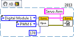
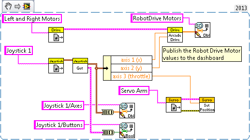
This snippet is an example of how to add Servo code into your application to control a robot arm. The particular servo configurations set up in Begin.vi allows you to control the robot arm in the Simulator using the throttle. Be sure to always properly open and close references within Begin.vi and Finish.vi.

If you are running short on being able to program and test your robot code don't forget about the LabVIEW FRC 2014 Simulator.  The 2014 Simulator provides the complete field layout for Aerial Assist to help simulate an actual game.  More information on how to use the FIRST Simulator can be found in the Robot Simulation Tutorial.

Begin VI

Servo Begin.png

Teleop VI

Servo Teleop.png

Finish VI

Servo Finish.png

Download All
Whit-E_Wall-E
9092 Views
0 Comments
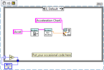
When programming your robot with LabVIEW, you may have some tasks that you only want to run occasionally in Teleop. In this snippet, the accelerometer is sampled and sent to the dashboard every 5 calls of the Teleop VI by incrementing number stored in a feedback node. This can be used to log data without having to run every time a status packet is sent to the DS.

If you are looking for more ways to incorporate or add an accelerometer to your application check out our online tutorial, Robot Framework.  This tutorial will step you through adding an Accelerometer to the Periodic Tasks VI.

reduced rate execution.png

Whit-E_Wall-E
6027 Views
0 Comments
Digital inputs, such as a limit switch, can be used to control movement of your servos.  To do this, wire a limit switch to a digital input on your cRIO, then use the digital input as control for a case structure.  Case structures allow your program to execute code depending upon certain conditions.  In this snippet, the case structure will move your servo motors when the switches are pressed.  The example code below shows two case structures, the first will move the servo motor forward to 180 degrees when one limit switch is pressed, the second case structure will move the servo backward to 0 degrees when another limit switch is pressed.

Looking for more information on sensor programing?  Check out these online tutorials about the basics of sensor programming and sensor fusion.

Digital+Input+Case+Structure+Control.png

Whit-E_Wall-E
9245 Views
0 Comments
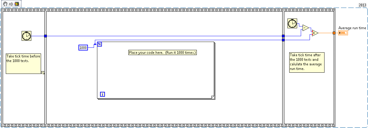
If you are worried about how long a chunk of code is going to take, or just want to quantify that run time, here's a quick and easy way to do it.  Drop the code inside the FOR loop in the snippet below, and calculate the average amount of time it takes to run the code.

This concept is called Benchmarking.  There are other ways of doing this as well.  See the following link for another strategy: http://www.ni.com/example/25532/en/

Benchmarking.png

Whit-E_Wall-E
5391 Views
0 Comments
There are many ways to use a motor besides driving your robot around. However, if you're already using the the axes of the joystick to drive the robot you will need another way to control additional motors. In this snippet we control the motor using the MotorControl palette instead of the RobotDrive palette. We set button 1 to turn the motor on when you hold it down, and buttons 2 and 3 on the joystick to decrease and increase the speed respectively. With this we can use a motor to rotate another part of the robot, such as an arm.

Note: When you first press button 1 on the joystick the speed is set to zero. You will need to use buttons 2 and 3 to cause the robot to reverse or move forward.

For more basic motor control and infromation on setting up your system check out this online tutorial.

Joystick Button Motor Control.png

Whit-E_Wall-E
4097 Views
0 Comments

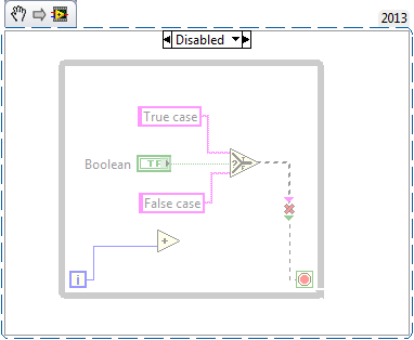
The Diagram Disable Structure is useful during development because you can disable or comment out sections of code. This allows the user to develop sections of code without it affecting the execution of the application. Only the code in the Enabled Subdiaram will execute. You can add more than one section of disabled code or enable a different code section by right clicking on the diagram and changing the settings.

In this snippet there is one section of disabled code and one section of enabled code. You can switch what section of code you wish to enable.

Don't forget about Context (Ctrl+H) and Detailed help when looking at functions that you want to learn more about.  The help files are also located online if you want to view the detailed help, but don't have LabVIEW on that computer.  Here is the help file for Diagram Disable Structures, but you can also search ni.com to pull up other HTML help files.

Diagram Disable Structure.png

Whit-E_Wall-E
4750 Views
0 Comments

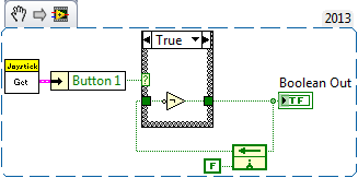
In LabVIEW when using Booleans you can generally adjust the mechanical action of the Boolean to be a switch or latch depending on how you would like it to respond when turned on.  However, with most joysticks all your Booleans will behave like a latch unless you continue to hold down the button so you can adjust for that programmatically using a Feedback Node and a Case Structure.  In this snippet when the joystick button is pressed it will stay true until the button is pressed again to turn the value back to false.  This can be used if you want a button to adjust something for an extended period of time and you don't have to continue to press the joystick button.

There is a similar example on how to complete this desired action in the NI Example Finder:  Help >> Find Examples >> Browse Tab by Task >> FRC Robotics Folder >> Joystick >> "Joysitck Button Latching.lvproj"

You can also learn more about the mechanical action of Booleans in the NI Example Finder: Help >> Find Examples >> Search Tab >> Enter mechanical as the keyword >> Select "Mecanical Action of Booleans.vi"

Boolean Button Stay True.png

Whit-E_Wall-E
7421 Views
0 Comments

We have already looked at Case Structures, but the LabVIEW Select function is another great tool to make programming decisions. A boolean value is connected to the select terminal. If the boolean value is high, the selector returns one value and if the boolean value is low, the selector returns a different value. You can use the selector to choose between values of many different data types such as boolean, strings, or numeric. For example, it is a great tool if you need to press a button to reset a device. If you push the reset button, the selector can choose to write the value to an initialized state. However, if the reset button was not pushed (the boolean value is false), you can choose to continue writing the value that was already there.  This snippet is also using the Feedback Node which we learned in a previous snippet to retain wire values each time the VI runs in the Robot Main.

For more LabVIEW tips and tricks check out this presentation found on the LabVIEW Training Page from ni.com/frc.

NumericSelector.png

Whit-E_Wall-E
7708 Views
0 Comments

Event structures can be used to react to user interaction with your VI. They execute code you create when certain events you select occur. These events can range from a mouse click on a front panel control, an indicator's value changing, or even someone trying to close your VI.

In this snippet there are four front panel controls with different symbols on them. Clicking on any of these symbols, while the VI is running, will cause the selected symbol to be displayed using an array of LED indicators. As an added bonus, you can also clear the display of the current symbol by putting your cursor on top of the array of LEDs and scrolling your mouse wheel in either direction.

If you would like to add more events to this example you can right click on the event structure on the block diagram and select "Add Event Case..." If you wish to delete events you simply select "Edit Events Handled by this Case..." instead.

Event structures may not be something you specifically use in LabVIEW with cRIOs, as you do not have the user interface to trigger events.  However, Event Structures are a great LabVIEW feature that is often used in LabVIEW programs.  What cool applications can you utilize Event Structures with?

Event Structure Snippet.png

Whit-E_Wall-E
4264 Views
0 Comments

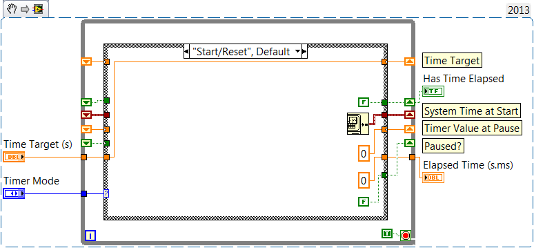
Functional Global Variables (FGV) are a great method of storing information. Because a true constant is wired to the stop condition of the while loop, values are saved in the shift registers of the while loop and are preserved when the VI is called again.

This FGV saves the system time in a shift register at the start of the timer. When reading the time, the current system time is compared to the system time at start. This particular FGV Timer allows for Start/Reset, Read, Pause, and Resume. It is important to note that FGVs must be called from a calling VI.

This FGV timer and FGVs in general can be applicable to much in FIRST Robotics. Any time you want to perform a certain function for a specified amount of time this will be useful.

National Instruments has a very active community outside of ni.com/frc that are always posting neat applications or example code they have developed to share with other LabVIEW users.  Here is a community example where you can automatically create FGVs through a quick drop keyboard shortcut.

FGVTimer.png

Here is a white paper on how to use a snippet in your program.

Whit-E_Wall-E
4000 Views
0 Comments

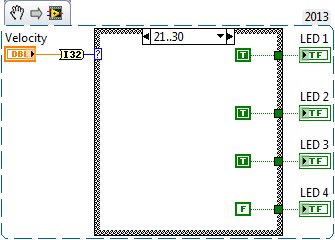
We can use the Case Structure in LabVIEW to make decisions based on an input to the Case Selector (the "?").  For example, if we wire a boolean value to this Case Structure, we can choose to run one algorithm if it is a true value, or another algorithm if it is false.

This snippet demonstrates how we can make decisions based on the value of a numeric control.  In this case, we can choose a different combination of LED values for five different ranges:

Less than or equal to 2

3 through 10

11 through 20

21 through 30, or

31 or greater.

This can be used, for example, to display more LED's to the driver when the vehicle's velocity is greater.  Note how you can change the range of values represented by each in case in the Case Structure.

Case Structure.png

Whit-E_Wall-E
8880 Views
0 Comments

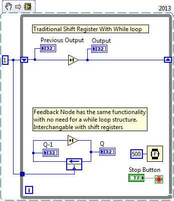
Shift registers and feedback nodes are used when you want to pass values from the currently executing iteration of a loop to the next one. This snippet demonstrates how they are both used and that they are functionally equivalent. The feedback node is a good candidate to be used in the Teleop sub VI where no loop structure is available to implement a shift register.

Interested in going through more training on LabVIEW Basics check out our Basic and Advanced Training slides here.

ShiftRegistersAndFeedbackNodes.png

Here is a white paper on how to use a snippet in your program.

Whit-E_Wall-E
8024 Views
0 Comments

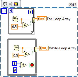
When writing code for autonomous operation, or even for portions of manual control, it's often necessary for the code to be able to react to an array of commands that will later be applied and interpreted for robot movement. However, it's also necessary to be able to filter that array of commands based on the scenario at hand. The ability to programmatically build arrays based on a condition/trigger is handled through the conditional auto-indexing tunnel. To enable the conditional terminal, right-click on the tunnel and select Tunnel Mode >> Conditional. In the example above, random data is being created, but only values over 0.5 are being placed into the array.This same technique could be applied to creating arrays of actions for the robot to take or filtering certain signals. This Boolean value can also be treated as a trigger, where we're only adding elements to the array when the trigger is high. The conditional auto-indexing tunnel can be used with both a for loop and a while loop, as shown above.

For more information on LabVIEW programming in general check out our free online resources here.

Conditional Auto-Indexing.png

Here is a white paper on how to use a snippet in your program.

Whit-E_Wall-E
4018 Views
0 Comments

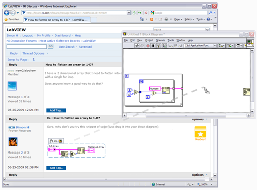
Every week on Tuesday and Thursday we will be posting LabVIEW Snippets to show different LabVIEW functionality and ways to enhance your LabVIEW Programs.  These snippets will range in basic LabVIEW tips and tricks, as well as more specific FRC LabVIEW functionality to enhance an example or help better utilize the different WPI Library functions.  With each post feel free to discuss the functionality and how you see it being used for FRC or programming in general!

How do you use a VI Snippet?

To add a VI Snippet to your block diagram, drag the image from file manager (such as Windows Explorer) or Internet Explorer onto a Block Diagram Window.

Using_a_VI_Snippet.png

Figure 1- VI Snippets make sharing code easy

Generally dragging and dropping an image file onto your block diagram will add an image decoration to your block diagram.  VI Snippets are special PNG images that have LabVIEW code in addition to the regular image data.  When you drop a VI Snippet onto the block diagram you get the depicted code added to your VI.