NI Circuit Design Community Blog

Community Browser
Labels
cancel
Showing results for 
Search instead for 
Did you mean: 
asloane
5643 Views
0 Comments

Hello Circuit Designers,

Are you going to NIWeek this year? This year marks the 21th year of the annual conference which brings together the brightest minds in engineering and science at the Austin Convention Center.

Banner.jpg

I wanted to let everyone know that there will be a special Multisim lunch and learn session taking place at NI Week 2015 on the new features and improvements in the latest release of Multisim. The session is on Wed Aug 5, 2015 and will be presented by our product experts and includes the following topics:

  • Keynote Speech
  • What’s New in Multisim and Ultiboard
  • Application Focused Designs
  • Open Discussion and User Feedback

Lunch will be served (compliments of NI.) The session is in meeting room 2 at the Austin convention center. Please confirm attendance before August 1, 2015 by responding to lee.hanna@ni.com.

Campbell B

National Instruments

asloane
6732 Views
1 Comment

Hello Circuit Designers,

NI Multisim version 14.0.0 includes an additional 500 new components with footprints and simulation models from International Rectifier.

Multisim FamilyDescriptionNumber of Components
DIODEDiode13
IGBTIGBT102
MOSFET_DRIVERMOSFET Driver54
POWER_MOS_COMPComplimentary N=P Channel Power MOSFET2
POWER_MOS_NN-Channel Power MOSFET353
POWER_MOS_PP-Channel Power MOSFET23
SCHOTTKY_DIODESchottky Diode45
Total592

Power MOSFETs Models

Some of the more noteworthy additions include Power MOSFETs such as single- and dual- N-channel and P-channel devices that offer fast switching speeds to meet a variety of power requirements. These devices can be used in applications such as:

  • AC-DC and DC-DC power supplies 
  • audio and consumer electronics 
  • motor control 
  • lighting and home appliances

IGBT Models

For Switched Mode Power Supplies designs, Multisim 14.0.0 includes over 100 new and updated IGBT components with footprints and simulation models.

Now in Multisim, you can accurately evaluate power electronics circuits built around International Rectifier IGBTs ranging from 300V to 1200V based on various technologies. You can optimize the design with powerful SPICE simulation to minimize switching and conduction losses and increase efficiency, reduce thermal problems and improve power density.

For a complete listing of new International Rectifier components vist this location.

Campbell B

National Instruments

asloane
7387 Views
0 Comments

Hello Multisim Users,

Just a quick note today to let everyone know that Multisim 14.0 has been released. This upgrade is free for users with an up-to-date Standard Service Program membership.

Added functionality includes all-new parameter analysis, integration with new embedded targets, and simplified design with user-definable templates. For the circuit designer there are 6,000 new components from leading manufacturers, a new active analysis toolbar to improve engineering workflow and enhanced voltage, current, power and digital probes.

mcu.png

For educators and students Multisim 14 comes with a new plug-in to co-simulate with Microchip’s MPLAB for simulation of complete circuits including PIC Microcontrollers (MCUs). Educators can combine the teaching of analog electronics, digital circuits, and embedded systems topics in a single software environment. Students can learn advanced concepts of real-world applications such as Pulse Width Modulation and LCD displays.

Over the next few posts I will be going in to more detail on these new features. Stay tuned.

Campbell B

National Instruments

asloane
5021 Views
0 Comments

Hello Circuit Designers,

I wanted to let everyone know about another great project done by one of our interns from Plymouth University working at National Instruments in the UK.  myMusicalTesla takes an audio signal as the stimulus, processing this with an NI myRIO embedded controller to switch a mini-Tesla coil and using the electric field generated to illuminate an unconnected fluorescent tube in time with the music.

The myRIO controls everything in this project - it takes audio input from its built-in audio jack, samples this data and performs an FFT on the onboard FPGA. Finally, it switches the Tesla Coil 100,000s of times a second in order to resonant the circuit. As well, another DIO line is used to pulse the circuit at the frequency of the note you wish to play. Everything is programmed in LabVIEW allowing quick coding and interfacing with the circuit board efficiently and easily.

myMusicalTesla.jpg

After designing the circuit in Multisim, the resulting design was transferred it to Ultiboard for PCB layout. To check out the full project with schematics, PCB layout and code visit this location.

Campbell B

National Instruments

asloane
4756 Views
0 Comments

Hello Circuit Designers,

I wanted to let everyone know about some great work done by one of our interns from the University of Manchester working at National Instruments in the UK.  myBall & Beam is based on the classic ball balancing systems control using myRIO as the controller, Multisim for schematic design and Ultiboard for PCB layout.

ball and beam.jpg

myBall & Beam uses an IR sensor to continuously detect the ball's current position and a servo to control the tilt of the beam. This information is analyzed on the myRIO's embedded processor to provide feedback to the system. To check out the full project with schematics, PCB layout and code visit this location.

Ball and beam schematic.jpg

Campbell B

National Instruments

asloane
4936 Views
0 Comments

Hello Circuit Designers,

Are you going to DesignCon this year? Held on January 27-30 at the Santa Clara Convention Center in California, DesignCon offers state-of-the-art design methodologies, applications and technologies for chip, board and systems design engineers. National Instruments will be exhibiting Multisim, VirtualBench and PXI systems. Check us out at Booth 507.

People.jpg

BTW, National Instruments is sponsoring the DesignCon Engineer of the Year 2015 award, which will be awarded on Wednesday January 28 at the show. The award includes a $10,000 grant that the winner can designate to his/her choice of institution of higher learning.

Campbell B

National Instruments

asloane
9336 Views
0 Comments

Hello Circuit Designers,

For those of you who may be new to NI Ultiboard our application engineering team has created a quick overview of features in Ultiboard and Multisim. You get a high level view on how to take a design from schematic through to printed circuit board layout.

3DBoard.jpg

For a more detailed introduction to NI Multisim and Ultiboard check out this whitepaper where you proceed step-by-step using Multisim and Ultiboard to capture, simulate and layout your design. To further your understanding you may want to visit the NI Multisim and Ultiboard Technical Resources page where you will find articles on simulation and advanced circuit analyses to theory and practice in PCB design.

Campbell B

National Instruments

asloane
5923 Views
0 Comments

Hello Circuit Educators,

I wanted to let you know about a great introductory video on using NI ELVIS II and Multisim. Within a few minutes you will see how to properly connect up the hardware and use the software to teach various electronics topics. As well you will see how the NI ELVIS and Multisim integration allows one to view circuits simulated in Multisim alongside a real world circuit on the NI ELVIS breadboard.

You can view the full YouTube video here. For more videos on Multisim topics check out this YouTube playlist.

Campbell B

National Instruments

asloane
11034 Views
0 Comments

Hello Circuit Educators,

I wanted to let you know that NTS press has a YouTube channel with tons of great videos on using Multisim and other National Instruments product such as LabVIEW, myDAQ and myRIO. In case you may not know, NTS Press is a division of National Instruments which specializes in publishing and distributing educational materials in engineering, science and mathematics.

NTS Press Logo.jpg

A sample of some of the Multisim getting started topics covered include:

  • Find the maximum value of a trace in Grapher View (go here)
  • Plot an expression combining two circuit variables (go here)
  • Export simulation data to Excel spreadsheet (go here)

To get to the NTS Press YouTube channel visit this page.

Campbell B

National Instruments

asloane
5021 Views
0 Comments

Hello Circuit Designers,

I wanted to share some exciting news about Multisim making the list of EDN Hot 100 Products of 2014 not once but twice.  Of the seven EDA tools that made the list Multisim Touch for iPad and Multisim Blue both made the list.

EDN100.jpg

Multisim Touch for iPad was released to the iTunes store in June and brings the intuitive Multisim SPICE simulation environment to the iPad. Multisim BLUE is a collaboration between National Instruments and Mouser Electronics. A key feature is the Mouser database, which is updated by Mouser Electronics, and provides a broad variety of up-to-date components from leading component manufacturers.

I can hardly wait to see what’s in store for 2015.

Campbell B

National Instruments

RichEMC
9643 Views
0 Comments

The latest upgrade to Multisim Touch includes interactive power source.  These are very useful.  Now have the ability to vary amplitude and frequency.  Issue is that this is not available in Multisim 13.  Are there any plans of having the same interactive sources for Multisim 13?

OStep
8696 Views
0 Comments

Not all SPICE models are created equal.

This saying applies especially to a model’s dependence on temperature.

Multisim allows the user to set the operating temperature of the simulation (the default is 27°C).  Using the Temperature Sweep analysis, Multisim even allows the user to sweep across a range of temperature values, running an underlying simulation such as DC operating point or Transient  for each step in the sweep.  However performing such an operation only makes sense if the models of the critical components in your circuit are designed to support temperature variation.

Let’s consider two BJTs with Model A and Model B.

Transistors.png

Let’s configure Temperature Sweep analysis to run a sweep from -55°C to 125°C and monitor the effect on beta, which we setup using an expression with the format I(ProbeN)/I(IbN) in accordance with the above naming of the probes and current sources.

TempAnalysis.png

The following is the result for Model A:

ModelAResult.png

This beta variation with temperature matches the part’s datasheet reasonably well.

The following is a result for Model B:

ModelBResult.png

This result does not match the part’s datasheet, which shows a much greater variation in Beta. In this case, it can be concluded that the model does not support temperature variation.

Notice that a model’s lack of support for temperature variation does not necessary imply that the results produced by the model will not vary with temperature. Clearly, as shown by model B, the temperature may play a role in shaping the model’s curves. A model’s lack of temperature support implies that simulating the model using a temperature different from which it was designed for will likely lead to incorrect results.  Models that do not support temperature variation are typically designed for 27°C, the default setting in Multisim.

Therefore, it is good practice to run a simple, isolated test on the model and compare the results against expectations before assuming the model supports temperature variation and using the model in circuit-wide temperature analysis.

asloane
8953 Views
0 Comments

Hello Circuit Designers,

I found another interesting white paper in the series on using simulation in the design flow that I wanted to share. In this case an EPC eGaN FET is used in various power conversion topologies utilizing models developed in collaboration with National Instruments and EPC. Although quantum-based effects are not incorporated, the models accurately reproduce the basic response of the devices under circuit operation conditions.

buck-boost topology.jpg

For more details on simulating with the EPC eGaN FET you should check out Design Efficient Fast Switching Power Converters with EPC eGaN FETs in our white papers. This paper demonstrates how Multisim best-in-class simulation can be used to enable accurate evaluation of overshoots, efficiency and power dissipation in switch-mode power supplies resulting in a more efficient design process.

Campbell B

National Instruments

asloane
4866 Views
0 Comments

Hello Circuit (and Engineering) Educators,

I wanted to let you know that National Instruments is offering a free webcast series that explores the latest solutions for hands-on learning. Spanning three days each webcast offers ideas and solutions on how to reinforce theory to provide the skills to needed succeed in research or industry.

19422_efg_virtual_event.jpg

Some of the topics that will be covered include:

  • Graduating Innovation-Ready Students With NI Teaching Solutions
  • Individual Webcasts on VirtualBench, myRIO, Software Defined Radio, Robotics and Mechatronics
  • Practical examples from the University of Texas, University of California, San Diego, Purdue University and others on their experiences using NI solutions in the classroom

To get more details and to register for individual seminars visit this page.

Let me know if you have any feedback or questions on this or any other Multisim topics.

Campbell B

National Instruments

asloane
5162 Views
0 Comments

Hello Circuit Designers,

As a circuit designer you rely on datasheets to define the specification of your design. Although they are an indispensable resource datasheets often lack detailed information on how parts will behave in different configurations.  Using Multisim SPICE simulation in the design flow can provide valuable insight into component behavior and reduce iterations.

For an interesting example on how simulation can be used in this manner you should check out Accurate Switched-Mode Power Supply Designs with NXP Components in our white papers. This paper, on the power stage of a DC-to-DC buck converter, uses Multisim SPICE simulation to determine how LC values effect ripple, the efficiency of the converter as well as using power dissipation to better understand thermal behavior.

Buck Converter.jpg

Let me know if you have any feedback or questions on this or any other Multisim topics.

Campbell B

National Instruments

asloane
9113 Views
0 Comments

Hello Circuit Designers,

I found an interesting article on using noise analysis which I would like to share. The article provides step-by-step details using an Analog Devices operational amplifier to demonstrate the benefits of using advanced analyses in your designs.

Noise analysis is a small signal analysis which is carried out at discrete frequencies using a linearized version of the circuit. In essence invisible noise sources are attached to every noise-generating element in the circuit and the analysis is performed against a reference voltage or current.

Noise Plot.jpg

Here is the complete noise analysis tutorial  that demonstrates in detail how to calculate total noise values, power spectral density curves and the model requirements when performing noise analysis.

Let me know if you have any feedback or questions on this or any other Multisim topics.

Campbell B

National Instruments

asloane
5072 Views
0 Comments

Hello Circuit Students and Educators,

I wanted to let everyone know about Digilent’s blog for students and educators. As you may know Digilent designs and manufactures engineering products, including digital and analog trainer boards, for technology based education.

LOGO-Digilent_Blog-250.png

This blog is an excellent resource for learning/cool projects using Digilent boards including FPGA boards, peripheral modules and USB based oscilloscopes, function generators and other instruments. Whether you are a student or educator looking for a class project or are into the makerspace community I’m sure you’ll find something of interest.

Let me know if you have any feedback or questions on this or any other topics.

Campbell B

National Instruments

asloane
5785 Views
0 Comments

Hello Circuit Designers,

The Multisim engineering team has just released an NI Multisim and Ultiboard user library with symbols and footprints for the NI Single-Board RIO System on Module. The Single-Board RIO System on Module, based on the Xilinx Zynq All Programmable SoC, combines a fully tested and validated hardware design that significantly reduces development time, design risk and time to market. For detailed specifications on the NI Single-Board RIO System on Module go here.

SOM.jpg

You will require Circuit Design Suite (Multisim and Ultiboard) version 13.0 (or later). The new user component library is merged with your existing Multisim library to add the additional symbols and footprints. Once merged you will find the component symbol and footprint in the User Database in the NI_Components group and the sbRIO family.

Part Placement.jpg

Let me know if you have any feedback or questions on this or any other Multisim topics.

Campbell B

National Instruments

asloane
9436 Views
0 Comments

Hello Circuit Designers,

How do you use Multisim in your workplace? I recently came across an interesting whitepaper on using Multisim, LabVIEW and PXI to verify the design of flight and optical electronics for a satellite system that I wanted to share with the community.

Design Flow.jpg

Due to the harsh conditions, i.e. outer space, in which the satellite would be operating the accuracy of this design was of utmost importance. There were three stages to the design flow:

  1. The design was captured and simulated in Multisim and presented to management for approval.
  2. The approved design was validated with LabVIEW and  Multisim
  3. The completed design was handed off to a layout team to build a prototype for further design validation

The final design prototype was connected to the PXI hardware. LabVIEW SignalExpress was used to acquire these real measurements. With real measurements being acquired through LabVIEW SignalExpress, and with the transfer of simulated data, we can correlate both sets of data. By viewing the differences between the data, the process of benchmarking and validating performance is easily done.

For the complete whitepaper on using Multisim, LabVIEW and PXI to effectively prototype a design see Flight and Camera Electronics for a Satellite System – A NI Multisim National Lab Application. For other interesting case studies and whitepapers on using Multisim in industry visit this location.

Campbell B

National Instruments

asloane
5901 Views
0 Comments

Hello Circuit Designers,

Are you going to PCB West this year? PCB West, at the Santa Clara Convention Center, brings together engineers, designers, fabricators, board assembly houses together for a one-day exhibition and three-day technical conference. We will be presenting NI Multisim and Ultiboard, Virtualbench integration as well as our new partnership with Mouser at the one-day exhibition happening Wednesday. Check out our booth below. If you are at the show drop by and say hello.

PCB West Booth 20140910.jpg

Let me know if you have any feedback or questions on this or any other Multisim topics.

Campbell B

National Instruments

asloane
5186 Views
0 Comments

Hello Circuit Designers,

For those of you who may be new to Multisim and Ultiboard our application engineering team have created a new tutorial on how to capture, simulate and lay out your first design. Building a basic amplifier circuit you proceed step-by-step using Multisim to capture and simulate your design. Lastly you transfer your design to Ultiboard for printed circuit board layout. Each step along the way is explained in precise detail.

Oscilloscope.jpg

I expect you will find it’s a good starting point on the road to becoming a Multisim and Ultiboard expert. To further your understanding you may want to visit the NI Multisim and Ultiboard Technical Resources page where you will find articles from simulation and advanced circuit analyses to theory and practice in PCB design.

Let me know if you have any feedback or questions on this or any other Multisim topics.

Campbell B

asloane
24199 Views
15 Comments

Hello Circuit Designers,

I thought you would like to know that our application engineering team has just released some Multisim user defined templates for creating custom Arduino shields. Each template includes a Multisim schematic with connectors to define inputs and outputs as well as an Ultiboard layout with the pin mapping and board outline. User defined templates are a new feature in Multisim and Ultiboard that provide a starting point to begin designing circuits and PCB layouts.

ArduinoBoard.jpg

Here's the list of the Arduino shield templates available:

        • Arduino Uno
        • Arduino Due
        • Arduino Pro
        • Arduino Ethernet
        • Arduino Leonardo
        • Arduino Mega 2560
        • Arduino MEGA ADK
        • Arduino Micro
        • Arduino Mini 05

You will need Circuit Design Suite (Multisim and Ultiboard) version 13.0 (or later). There is a new user component library that you merge with your existing library to add the additional symbols and footprints used in the template. For a detailed tutorial on using the new templates for creating Arduino shields go here.

Let me know if you have any feedback or questions on this or any other Multisim topics.

Campbell B

National Instruments

asloane
5271 Views
0 Comments

Hello Circuit Educators,

Are you using NI Multisim in your real or virtual classroom? Educators worldwide use Multisim to teach foundational and advanced topics in analog, digital, and power courses in colleges and universities. For instance Georgia Institute of Technology has incorporated Multisim with NI ELVIS to create a combined software and hardware laboratory where students can simulate circuits to gain a deeper understanding before the lab and use the hardware measurements to reinforce theoretical concepts.

studenta.jpg

To learn more about teaching applications using Multisim, including the complete Georgia Institute of Technology case study click here. You will find Multisim courseware and curriculum here. These resources are broken out by area of study, e.g. analog, digital or power and academic year.

Let me know if you have any feedback or questions on this or any other Multisim topics.

Campbell B

National Instruments

asloane
5483 Views
0 Comments

Hello Circuit Designers,

Do you design Switch Mode Power Supplies (SMPS)? NI Multisim SPICE simulation includes support for a variety of models for MOSFET and IGBT switches from leading semiconductor manufacturers.

Power Circuit.jpg

In Multisim 13.0 new customizable diode, IGBT, and MOSFET components with thermal behavior information have been added. These components allow you to accurately evaluate conduction and switching losses, as well as the thermal behavior of SMPS.

For more details on using NI Multisim to design SMPS and working with power electronics in general see Power Electronics Design with NI Multisim.

Campbell B

asloane
5217 Views
0 Comments

Hello Circuit Designers,

Multisim was presented as part of the Hybrid Automotive HIL (Hardware-in-the-loop) presentation on Day 2.  It briefly demonstrates downloading a SPICE simulation to an FPGA, and then using the FPGA solver to run the simulation. With this feature you export the matrix for a subset of specialized models and use this matrix to simulate the circuit on an FPGA using Hardware-in-the-loop simulation which greatly speeds up verification of designs. The supported models include the ideal switch, diodes, capacitors, inductors, transformers and resistors. Essentially a lot of the elements that go into switch mode power designs which is what this will initially be used for.

You can watch the entire Day 2 keynote presentations here or skip forward 52 minutes to see the Multisim presentation. If you are interested there is an NI Labs paper with complete details on this new feature coming soon.

Lastly, if you want to know more about NIWeek I would encourage you to check out some of the other cool/interesting videos on the National Instruments YouTube channel.

Campbell B

National Instruments

asloane
7899 Views
0 Comments

Hello Circuit Designers,


Today I want to highlight a relatively new Multisim feature using interactive simulation that you may not know of. A virtual instrument created in LabVIEW can be used to connect real-world signals to Multisim or output simulation data to drive real-world circuitry. You can build either an input instrument where Multisim inputs data to a LabVIEW instrument or an output instrument in which LabVIEW outputs data to Multisim.


LabView VI in Multisim.jpg


A LabVIEW input instrument continuously receives data from Multisim while the simulation is running. You can then connect simulation results to real-world I/O such as DAQ, GPIB, Serial, File, and the like. A LabVIEW output instrument uses data that is acquired beforehand which is then used when the simulation is running. This means that data acquisition has to take place before you start a SPICE simulation (for example, first record data with the microphone and then start the simulation).


To create a LabVIEW virtual instrument for use in Multisim you use LabVIEW to create a Front Panel with the appropriate controls, coding and save as a custom instrument. Then, using Multisim you place the new custom instrument on your schematic, connect the terminals and run your simulation.


In order to simulate with a custom LabVIEW instrument you will require Multisim version 12.0 or later and LabVIEW 8.x or later to create the virtual instruments that you will use. You only need LabVIEW to create the instrument. LabVIEW does not need to be installed on the machine where you intend to run Multisim. 


Let me know if you have any feedback or questions on this or any other Multisim topics.


Campbell B


National Instruments

asloane
5731 Views
0 Comments

Hello Circuit Educators,

Our new application engineering intern has been busy the last few weeks churning out reference designs and templates for some of the more popular Digilent boards. For those who may not know Digilent designs and manufactures electrical engineering products including digital and analog trainer boards for technology based education. For a great introduction to working with Digilent Boards in Multisim click here.

chipKITs-260.png

The following designs and templates are available:

You will require Circuit Design Suite (Multisim and Ultiboard) version 13.0 (or later) to be able to utilize these resources. There is a new user component library that you merge with your existing library, which adds the additional symbols and footprints used in the reference design or template. User defined templates are a new feature in Multisim and Ultiboard that provide a starting point to begin designing circuits and PCB layouts. With a template various elements such as connector placement, critical devices and board layout can be pre-configured to aid in the design process.

Let me know if you have any feedback or questions on this or any other Multisim topics.

Campbell B

National Instruments

asloane
5146 Views
0 Comments

Hello Circuit Designers,

Are you going to NIWeek this year? Held every year in early August this NIWeek will be the 20th annual conference which brings together the brightest minds in engineering and science at the Austin Convention Center.

NIWeek 2014.jpg

I wanted to let everyone know that there will be a special session on the new features and improvements in the latest release of Multisim. The session is on Wed Aug 6, 2014 and will be presented by our product experts and includes the following topics:

  • Keynote Speech
  • New Multisim Touch on the iPad
  • What’s New in Multisim and Ultiboard
  • Application Focused Designs
  • Open Discussion and User Feedback

Lunch will be served (compliments of NI.) The session is in room 10A at the Austin convention center. You will need to confirm attendance before August 1, 2014 by responding to lee.hanna@ni.com.

Campbell B

National Instruments

asloane
10029 Views
0 Comments

Hello Circuit Designers,

One thing I recently noticed is that there are a lot of Multisim resources out there but they’re not always that easy to find. I thought it would be useful to point out some of them today. To begin with here is the National Instruments landing page for Multisim. It has the usual wealth of product information but for our purposes we will explore some of the other Multisim resources that are available from this and other locations on ni.com.

MSM-puzzle.jpg

The introductory page NI Multisim and Ultiboard Technical Resources has getting started tutorials on Multisim and Ultiboard, how to get technical support as well as more advanced discussions such as SPICE simulation fundamentals and PCB layout best practices.

If you are looking for concepts, circuits and simulations you should visit the National Instruments Circuit Design Technical Library. This is a fairly comprehensive source for schematic design, SPICE simulation concepts and advanced simulation discussions including incorporating LabVIEW measurements into Multisim. As well you will find a good collection videos of NI Multisim Technical Help Videos available.

For in depth discussions on Multisim, Ultiboard and NI ELVIS check out the White Papers section. This area is updated often so you should check back frequently. A quick search on the term Multisim turns up almost 400 hits with topics such as detailed application notes, integrating Multisim and NI ELVIS, as well as a plethora of courseware. More Multisim courseware, broken down by year of study and application, can also be found here.

National Instruments maintains two Multisim specific communities National Instruments Circuit Design Community (this location) and Multisim Custom Simulation Analyses and Instruments. The latter location has a large set of custom instruments and analyses for use in Multisim that were developed in LabVIEW and are geared towards specific engineering applications such as system control, audio signal processing, noise analysis, and power design.

I hope this quick overview has provided you with a good basis for your exploration of circuit design and simulation with Multisim. Let me know if you have some favorite sources for circuits, models or other Multisim resources that you would like to share.

Campbell B

National Instruments

asloane
5115 Views
0 Comments

Hello Circuits Educators,

As you may know Multisim Touch for iPad was released June 9 on iTunes. If you haven’t heard Multisim Touch for iPad is the newest edition to the Multisim lineup that provides engineers, educators and students a platform to design and simulate analog circuits anywhere. This circuit design app allows users to quickly build circuits with a library of common devices and visualize the performance in an interactive graphical environment. Over the past few weeks we’ve had a good response with many positive comments worldwide.

  Touch Circuits.jpg
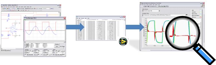
Today I wanted to share some additional resources for getting started as well as some interesting courseware. This location is the starting point for all things Multisim mobile. If you scroll down the page to the Technical Resources section there are many videos and circuit examples for use with Multisim Touch for iPad. For example, the Getting Started videos cover the basics from building a design to simulating and analyzing a circuit. You can download the Getting Started Circuits directly to the iPad and begin simulating right away.

Multisim Touch for iPad is part of the NI Circuits Teaching Solution which provides an integrated environment for simulation and circuit design across tablets, desktops and teaching hardware. The Multisim Touch Courseware Examples section of the Technical Resources page contains over 30 circuits for first and second year analog circuits courses. These circuits are based on existing Multisim courseware and provide a great starting point for creating, simulating and analyzing circuits on Multisim Touch.

Please let me know if you have any feedback or questions on this or other Multisim topics, or on how you plan to use Multisim Touch in your classroom.

Campbell B

National Instruments