From Friday, April 19th (11:00 PM CDT) through Saturday, April 20th (2:00 PM CDT), 2024, ni.com will undergo system upgrades that may result in temporary service interruption.

We appreciate your patience as we improve our online experience.

NI Circuit Design Community Blog

Community Browser
Labels
cancel
Showing results for 
Search instead for 
Did you mean: 
Mahmoud_W
14359 Views
2 Comments

Hello Circuit Designers,

With the recent release of the new General Purpose Inverter Control (GPIC), I am pleased to introduce you to this new power inverter implementation grabbed the attention of a lot of design experts in the renewable energy segment during NI Week this year.

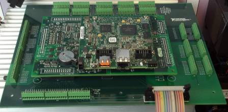
The general idea is for the Single-Board RIO 9606, the GPIC 9683, and a mating board to form a stack of 3 PCBs for inverter control.  This inverter stack allows the 3 PCBs to act as a single system with multiple functionalities:

1. The Single-Board RIO features a user programmable FPGA and a PowerPC processor. 

2. The GPIC offers a complete set of I/O, using common electronics control applications. The controller and the I/O board are connected together using a RIO Mezzanine Connector (RMC); this provides high speed, high bandwidth length between the I/O on the GPIC and the FPGA on the Single-Board RIO.  

3. The GPIC mating board connects directly to six female Insulation Displacement Connectors (IDC) headers at the bottom of the GPIC and provides connectivity to the 6-pack inverter load, as well as break-out of the simultaneous AIs, scanned AIs, LVTTL DIOs, Sourcing DIs, Sinking and Relay DOs, and Half-Bridge DOs.  The mating board was developed to save you days of development for a custom inverter interface.

GPIC+breakout+board+with+SKiiP+3+connector.jpg

The mating PCB for the GPIC platform was fully designed in Ultiboard and a template of that design is made available for all NI power electronics customers HERE!

The features of this example GPIC mating board including the following:

  1. Screw terminal breakout connectors for each GPIC I/O connector
  2. 26-pin IDC Semikron SKiiP 3 connector, allowing you directly connect to large inverter cables
  3. Powered by external 15 VDC regulated supply; extra terminals available for jumpering power to the Single-Board RIO using 2-position mini-fit power plug pigtail wire assembly
  4. Shunt resistor pads for all analog inputs
  5. Preservation of ground plain and trace keep-out spacing distances for functionally isolated simultaneous analog inputs
  6. Relay signals isolated to reduce high current and noise.
  7. Digital I/Os matched to traces at certain impedances to account for high speed currents
  8. Follows simultaneous analog input pseudo-differential grounding scheme recommendations
  9. Thick 0.093” PCB for mechanical strength
  10. 0.040” plated holes for SH2 mating connectors for proper IDC connector mechanical alignment
  11. Keepout spacing on all sides suitable for extraction crowbar tool
  12. Keepout area for HALO transformer; no components can be placed underneath

NI Multisim's team continues to invest in power electronics applications and would be happy to hear your feedback about it.

Mahmoud W

NI

Mahmoud_W
12972 Views
0 Comments

Hello Circuit Designers,

Creating connector symbols and footprints is time-consuming, and even the smallest mistake on pin spacing, definition, or overall sizing results in prototype errors. For instance, an engineer could spend up to two days creating and testing the RIO Mezzanine Card (RMC) connector, a high-density 240-pin SEARAY connector used in some NI Single-Board RIO systems.

Using Multisim and Ultiboard for accessory design can save you days of development and reduce prototype iterations instantly. Multisim 12.0 has an expanded library of hardware connector symbols and footprints for NI hardware such as NI DAQ, NI CompactRIO, and NI Single-Board RIO.

These connectors are under the component group called NI_Components in Multisim:

Success Story

Taking advantage of the optimized circuit simulation and prototyping environments of Multisim and Ultiboard, one of Multisim's lead users, Cyth Systems, developed a ready-to-use, technically proven signal conditioning circuitry that can rapidly integrate daughterboards and daughterboard kits into Single-Board RIO for medical and biotech applications.  Cyth Systems designers were able to rapidly produce the Circaflex boards with few design iterations.

Let me know if you have any feedback on custom board design applications, or if you have a success story you would like to share with everyone!

Cheers,

Mahmoud W

National Instruments

Mahmoud_W
23200 Views
4 Comments

Hello Circuit Designers,

The Multisim team works closely with the rest of the design segment at NI, at addressing how our tools can help engineers in different industries such as the Automotive segment.

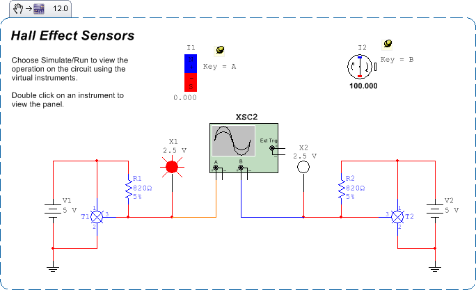
Today, I want to share with you a circuit that simulates the operation of a Hall Effect Sensor (HES) widely used in Automotive and Industrial applications. In principle, a HES produces an output voltage (AC or DC) that is proportional to a magnetizing flux. This concept could be implemented in many applications such as:

- Current sensors and transducers

- Position and motion sensing

- Automotive ignition and fuel injection

- Wheel rotation sensing

Here is the design, try simulating it in Multisim and let me know how it fits your application.

Cheers,

Mahmoud W

National Instruments

HES2.png

GarretF
13444 Views
2 Comments

Last week I described how to achieve design reuse for LabVIEW-Multisim co-simulation using variants, and promised to describe how to achieve the same thing using hierarchical blocks the week after. Our goal was to be able to use only one design, whether for LabVIEW-Multisim co-simulation, Multisim-only simulation, or transfer to Ultiboard for layout.

Hierarchical Blocks

The HB/SC connectors that you use for co-simulation are the exact same connectors that you use for hierarchical designs. By using the exact same connectors, the design you have for co-simulation is already setup for hierarchical designs, so our first step is to create a container schematic to host the design.

File > New Design

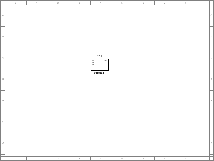
Next, we will place the primary design as a hierarchical block in this container (Place > Hierarchical block from file...). If your using the summer example, you can file the same at C:\Users\Public\Documents\National Instruments\Circuit Design Suite 12.0\samples\LabVIEW-Multisim Co-simulation\summer.ms12.

hb_with_summer.png

Our design looks a little sparse, so let's add some sources to drive the input connectors and a scope to show the output.

hb_complete.PNG

For LabVIEW-Multisim co-simulation, just simulate as normal. For Multisim-only simulation, select the container design, and simulate. For transfer to Ultiboard, open the summer design, and transfer as normal.

I've attached the complete design as a Multisim packed project.

GarretF
11800 Views
0 Comments

Back when we were designing LabVIEW-Multisim co-simulation, we talked a lot about workflow, and what you see today is one of several options we explored. One of the important factors we considered was how someone would go from iterative design to implementation on a PCB. We wanted that to be seamless so that you wouldn't have to recapture any part of your design. For example, if layout required a change to the design, you could change it in once in Multisim, and it would immediately be reflected in co-simulation.

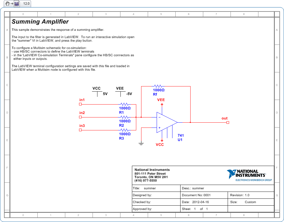
Brian MacCleery's blog discusses these approaches, but I though I would add my input. We envisioned two approaches to seamless design with co-simulation - which one you choose depends entirely on personal preference. The summer example file is probably my favourite example because it is so simple, yet demonstrates the power of this approach so clearly.

summer.png

Here we have a design with HB/SC connectors are already setup for co-simulation. But what if you want to simulate only in Multisim? How do you do this without changing your design so that you can seamlessly switch back and forth between Multisim-only simulation and LabVIEW-Multisim co-simulation?

When you co-simulate, the input HB/SC connectors are driven by LabVIEW. When you simulate only in Multisim, you therefore need to supply a substitute driving signal on the input HB/SC connectors. Given this posts title, you might have guessed the way to achieve this is through hierarchical blocks or variants. Which one you choose is entirely up to you and your personal preference, although my personal preference is hierarchical blocks.

Variants

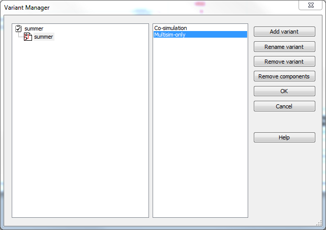
First, let's add some variants to the design. In the Variant Manager (Tools > Variant Manager), rename Default1 to Co-simulation and add a new variant Multisim-only. Once you are done, your variant manager should look like the following:

variantsmanager.png

Next, add some sources to your design to drive the input HB/SC connectors. You can use any source you like, and I've put a variety on the design.

summer_with_sources.png

Finally, for each of the sources, edit the properties, and exclude it from the Co-simulation variant, and include it in the Multisim-only variant.

variant_properties.PNG

When your done, you'll have created the following design (it looks the same as the last design, but the sources now have different variant settings).

summer_complete.png

Switching between the Co-simulation and Multisim-only variants in the Design Toolbox adds/removes the sources from simulation.

design_toolbox.PNG

For LabVIEW-Multisim co-simulation, select the Co-simulation variant, save the file, and run the simulation from within LabVIEW. For Multisim-only simulation, select the Multisim-only variant, and run the simulation from within Multisim. To take this design to Ultiboard, use the normal method and only select the co-simulation variant. Transfer to Ultiboard will exclude the sources anyway because they don't have footprints, but I like to exclude them because it makes more sense to me.

So that's how you use variants to reuse the exact same design for LabVIEW-Multisim co-simulation, Multisim-only simulation, and tranferring to layout. Next week I'll describe how to achieve this using hierarchical blocks.

Mahmoud_W
10717 Views
0 Comments

Hello Circuit Designers,

NI tries to offer a complete design solution that helps engineers in many application areas from power electronics, to automotive, to clean energy to effectively simulate, prototype, and deploy their designs.

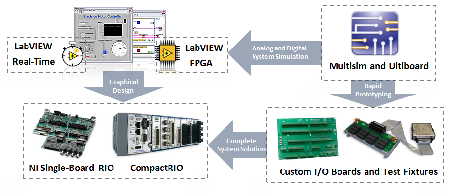
For motor control applications, the co-simulation feature with LabVIEW is a valuable addition on the simulation side. Engineers can model a complete system of analog circuitry and digital control code at the desktop level then easily deploy the code a target chip (such as FPGAs) and using Ultiboard quickly prototype the analog circuitry on PCB.

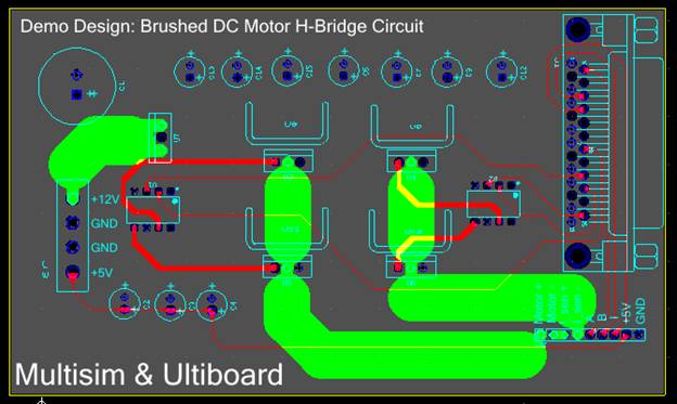
I have recently published this tutorial showing a PCB design of a motor control H-Bridge circuit that ties into a Compact RIO controller where the initial system simulation was accomplished using Multisim and LabVIEW.

That PCB design is part of the NI design solution, that I just mentioned, and summarized in the figure below.

Enjoy,

Mahmoud W

National Instruments

ddd.png

GarretF
15956 Views
0 Comments

I've been asked quite a few times how to easily upgrade files from an older version of Multisim to the latest version. Years ago, I created a simple utility to open and save the files in a single directory, but since Multisim 11, you can use Multisim directly to upgrade files to the latest version.

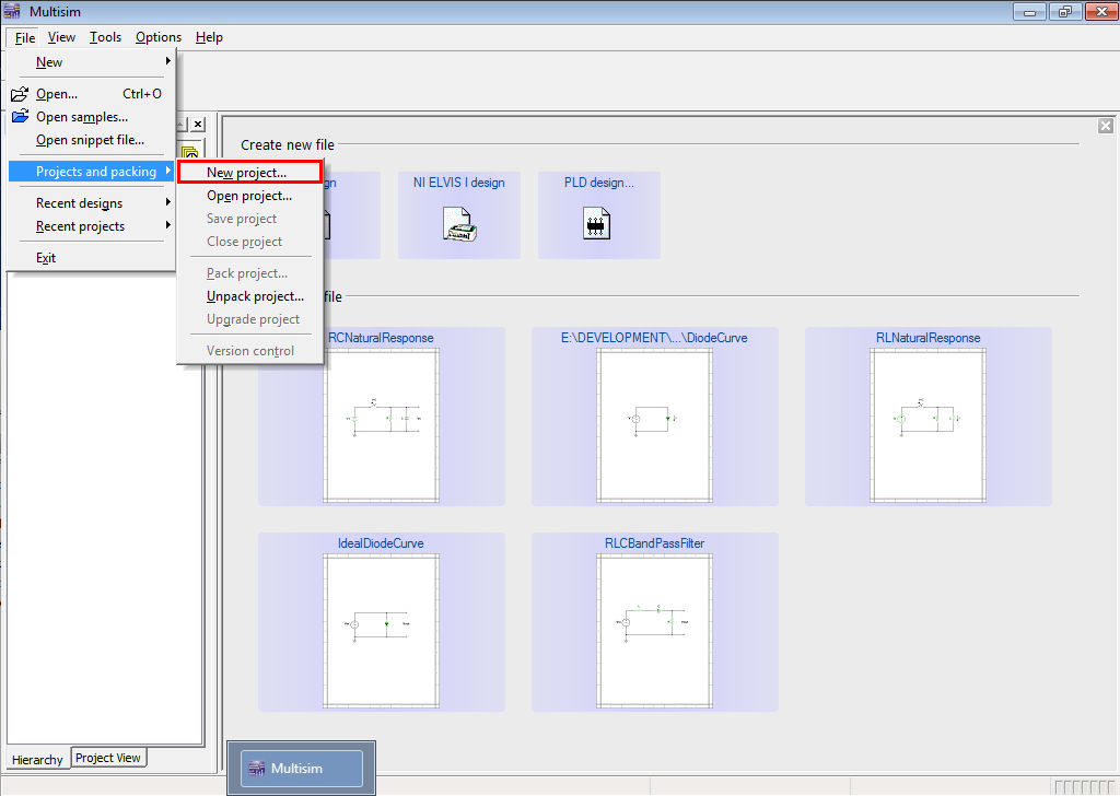
Multisim 11 introduced packing projects into a single distributable archive. Project packing also included a lesser know feature: Upgrade project. Upgrade project converts all Multisim files in a project to the latest version - all in a single step. This is great if you have a large number of Multisim files (for example files developed for a course) that you need to upgrade. Even if you don't have a project, you can create a temporary project that you use to upgrade your files.

Follow the steps below in order to upgrade a set of files to the latest Multisim version.

1. Click File > Projects and packing > New project

New Project.png

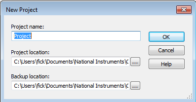
2. Accept the default project

New Project2.png

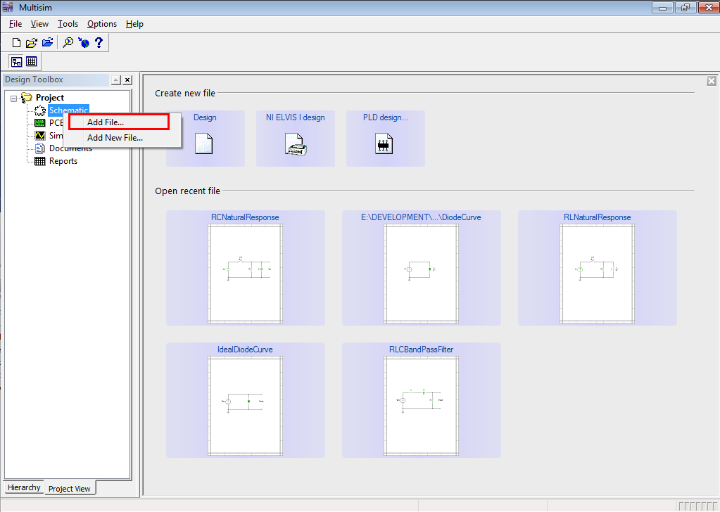
3. In the Project View, right-click Schematics, and click Add File...

Add Files.png

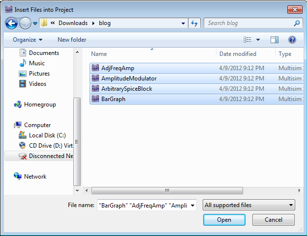
4. In the Insert Files to Project dialog, select the files you want to upgrade. Note you can use Ctrl and Shift to add multiples

Add Files2.png

5. Finally, click File > Projects and packing > Upgrade project

Wait a few moments and the files are upgraded.

GarretF
10486 Views
0 Comments

This post is part of a series on what's new in Circuit Design Suite 12.0


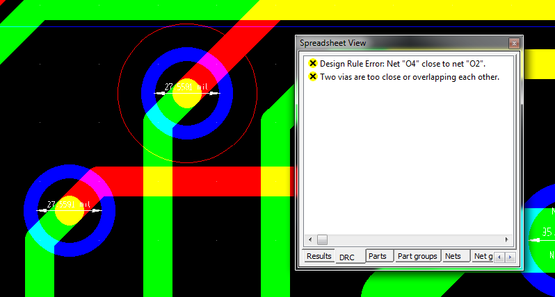
Version 12.0 includes a new DRC check for overlapping vias. (Ultiboard always had a check if copper objects were too close such as vias were to close, but there is now an additional check specific for vias that will detect if the vias are connected.) Now, if two vias are within the via-to-via clearance and are drilled such that they go through at least one common layer, Ultiboard will highlight this condition as a DRC error.

ViaDrcCheck.png

As before, if you don't want to see this class of errors, you can hide the error using the Filter Manager by right-clicking in the DRC tab and selecting Filter Manager.

GarretF
10288 Views
0 Comments

This post is part of a series on what's new in Circuit Design Suite 12.0

Some time ago I wrote about some advanced selection techniques in Ultiboard, and in particular the right click+drag selection options. I mentioned at the time how a long time user had learned of some new functionality, but I didn't mention why we were discussing it. The reason is because I was adding a new item to the right click+drag selection options.

Previously, the right click+drag extended selection options allowed you to only select objects if they were on a particular layer. Some objects, such as vias and parts, are on more than one layer, and it was not possible to use these extended selection options for these types of objects. This new option allows you to pick precisely which items in the selection area you want to selected. With the new Select specified objects... option, the rectangle narrows down the possible choices so you can pick from a reduced set.

As before, right click+drag to select the area where the object(s) you want to select are located.

SelectSpecifiedObjects.png

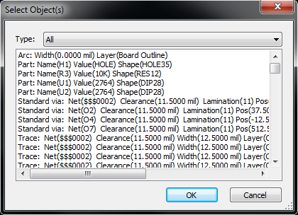
Click the last item in the menu, and the Select Object(s) dialog appears

SelectedObjects.png

Each object in or crossing the rectangle is listed in the dialog with a short description of the object, and you can pick the object(s) of interest. They are even categorized by the object type, so if you change the Type, you get a further filtered list of objects to choose from.

Mahmoud_W
16163 Views
0 Comments

Hello Circuit Designers,

I've been recently looking into motor control designs, widely used in energy and automotive applications, and the reason for that is to learn more about how the new capability of accurate system simulation at desktop level using Multisim 12 and LabVIEW 2011 can be successfully implemented in this application area.

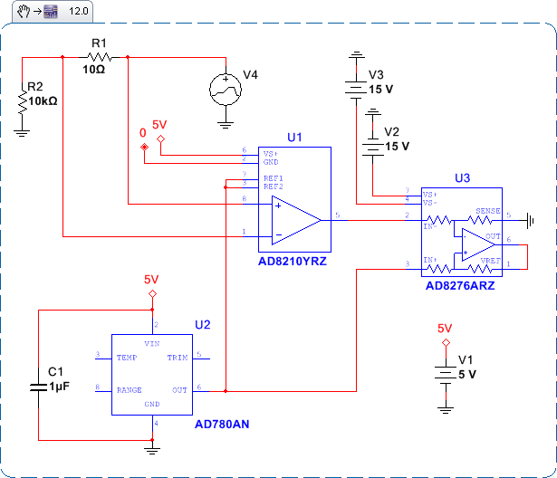
What caught my attention is the numerous pure analog circuits that are essential for these types of designs (motor control), apart from the main switching plant that requires digital logic/FPGA control. A good example is a high-precision current monitoring circuit. I came across this circuit that simplifies high side current monitoring by providing a high voltage interface and bidirectional current monitoring capability across a shunt resistor while using a single supply.

In no longer than half an hour, I was able to lay-down a schematic, simulate, and validate a design based on an Analog Devices circuit note and using their industry-standard SPICE models available in the Multisim's database for the following parts:

  • AD8210:  High Voltage, Bidirectional Current Shunt Monitor.
  • AD780:  2.5 V/3.0 V Ultrahigh Precision Bandgap Voltage Reference.
  • AD8276:  Low Power, Wide Supply Range, Low Cost Unity-Gain Difference Amplifier.

The circuit schematic is shown in the following snippet (png image) which you can drag and drop directly into Multisim 12.0:

adi1.png

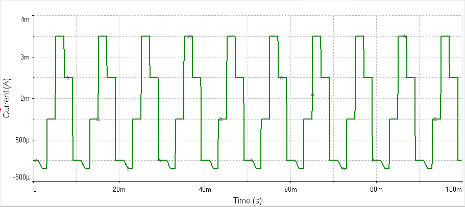
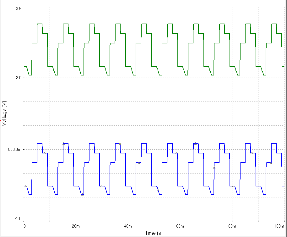
The following graphs show the transient response of the input load current and how the integrated current sensing device AD8210 responds and generates a proportional voltage that is level-shifted at the ouput stage of the AD8276.

adi2.png

adi3.png

Let me know your thoughts/feedback regarding this type of application.

Enjoy!

Mahmoud

National Instruments

GarretF
10653 Views
0 Comments

This post is part of a series on what's new in Circuit Design Suite 12.0


The board outline in Ultiboard delineates the boundary of your design. Parts are usually placed within the board outline, and power planes end at this boundary. The board outline therefore needs to be a valid closed shape for Ultiboard to do a variety of things, such as automatically place parts within this boundary. (Without a boundary, how do you place things inside it?) Typical situations that arise that cause an incorrect board outline would be line end points that are not quite touching (as in top left corner of the image below), or overlapping lines, and these tend to arise when importing the shape from another program.

IncorrectBoardOutline.png

This release has two small but very useful improvements to help with these situations.

Reporting Problems

Previously, Ultiboard would detect the problem and tell you about it, but didn't provide any help if you wanted to fix the problem yourself. It was up to you to scrutinize your design and figure out where the problems were. Now, when Ultiboard detects an incorrect board outline, you can get a list of all of the problems to quickly figure out where the problem is.

DanglingObjects.png

Automated Fixing of Problems

In some situations, Ultiboard would offer to automatically fix problems, and this has been completely rewritten to give much better results. It will now detect and merge overlapping line segments. It also now maintains orthogonality of segments so vertical lines remain vertical and horizontal lines remain horizontal.

Mahmoud_W
10703 Views
0 Comments

Hello All,

With the recent release of NI Multisim, our development team have been working tirelessly to enhance and optimize our core SPICE simulation engine, as well as our overall design/prototyping environment. Part of the enhancements to our latest release can be seen when comparing the performanace of the recent release of Multisim 12.0 with previous editions such as Multisim 11.0.

The improvements we mention below are based on some in house benchmarking tests and can be considered as approximate improvements. The changes that you will see, may differ based upon a number of factors. I would personally love to hear your feedback - so please send me a message at mahmoud.wahby@ni.com.

1. Transient Simulation Time

In order to understand how Multisim was able to run a transient simulation, the following circuits where chosen for a number of benchmarking tests:

  • Half Bridge Driver
  • NCP1380 Modded Switch
  • Instrumentation Amplifier
  • Gilbert Cell Mixer

On average we saw that the time it took to run a transient simulation was reduced by approximately 52%.

2. Reduction of PCB Export File Size and Autorouting Time

The handling of copper areas, curved lines, and traces have been significantly improved in Ultiboard 12.0. The net result has lead to a significant reduction in the size of exported files (such as Gerber and DXF) as well as the time to autoroute board.

  • Size of exported Gerber files is reduced by approximately 50% on average
  • Size of exported DXF files is reduced by approximately 94% on average
  • Auto-routing time reduced by approximately 30% on average

3. Loading of Custom Analyses and Instruments

In Multisim you can develop custom simulation analyses using Virtual Instruments (VIs) developed in NI LabVIEW. In fact some great new custom simulation analyses can be found in our community for free downloads by clicking here.

Loading a large number of these analysis instruments (for example 10) in a single schematc could take as much as 19 seconds to open in previous editions of Multisim. In version 12.0 we were able to record 50% improvement in the loading time for various types of instruments.

You can see all of these improvements listed below

FeatureAverage Improvements
Simulation of transient analysis (Time)~52.31%
Decrease in size of DXF file~94.14%
Decrease in size of Gerber files~50.23%
Loading time of custom analyses (10 LabVIEW instruments)~50.43%
Autorouting Time~29.94%

Again the improvements that you will see in your simulation and design time may vary based upon a number of factors, but we certainly have seen some great improvements in our benchmark tests. Please message me at mahmoud.wahby@ni.com about the improvements you have seen, and whether you have further questions about how Multisim 12.0 can enhance your current design or simulation environment.

Thanks!

Mahmoud

National Instruments Toronto

GarretF
11270 Views
0 Comments

This post is part of a series on what's new in Circuit Design Suite 12.0


When you select a number of different objects in Ultiboard, then rotate that selection, the selection rotates about the center of the selection. This is pretty important because if your selection contains traces and other objects. If instead of rotating as a group, Ultiboard instead rotated about each objects individual center, rotation might turn

BeforeRotation.png

into

RotatedBadly.png

Yikes! Definitely not what you would usually want. So Ultiboard does the right thing and rotate about the centre of your selection. But suppose you do want to rotate about individual centres, for example because you want to rotate a few of RefDes, as in the following case

RotateOriginal.png

In this case, I want to rotate them about their individual center. Or suppose you wanted to create the second image above. How would you do that? Before version 12.0, you would select each object individually and rotate it, but now there is a better way.

  1. Select the objects to rotate
  2. Edit > Orientation > Rotate...
  3. Select Rotate about individual centers

RotateDialog.png

Click OK, and you'll get

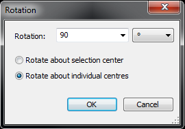
RotateGood.png

Mahmoud_W
19471 Views
0 Comments

Hello Circuit Designers,

As you may already know, NI Multisim uses SPICE as its core algorithm for solving differential equations that model circuit components. The Multisim development team has put great efforts in enhancing this simulation environment and adding features to it for optimized analog and mixed-mode simulations.

Of course, the accuracy of the results depends on the settings of the SPICE simulation. This is why the default simulation settings in Multisim define tight enough conditions to assure quality results. In some cases, the circuit might be too complicated for the SPICE simulator to converge with the default settings and this is why the convergence assisstant is also included in Multisim. I am sure many of us just click "yes" once the convergence assistant dialog box shows up for the first time. And this is why I decided to write this blog post, to take a deeper look at what it actually does.

spice1.PNG

A convergence problem means that the difference (in voltages) between the simulation results of one iteration and the following one are not small enough implying an inaccuracy in the given solution. What the convergence assisstant does is changing some of the important simulation parameter that might be the cause of the problem to help the circuit converge, or in other words obtain consistant results between consecutive iterations.

Below is a list of these parameters and their significance

SPICE ParameterSignificance
METHODSets the time step integration method.
Setting Initial Conditions to ZeroThis step sets all the voltages of the circuit to zero as an initial condition for the solution.
TMAX

TMAX is the maximum stepsize that SPICE uses; for default the program will choose the smaller of either Tstep or (Tstop-Tstart)/50.0. TMAX is useful when one wishes to guarantee a computing interval which is smaller than the printer increment, Tstep.

RELTOLSets relative error tolerance of the program. The value must be between 0 and 1.
RSHUNT

Value (in ohms) of resistors added between each circuit node and ground, helping to eliminate problems such as "singular matrix" errors. In general, the value of RSHUNT should be set to a very high resistance (1e+12).

ITL1

Sets Operating Point Analysis iteration limit.

GMINSets min conductance (max resistance) of any device in the circuit (in mhos). Also sets value of the conductance that is placed in parallel with each pn junction in the circuit.

And here are some screenshots of the convergence assisstant of Multisim trying to fix one of my circuits!

Capture4.PNG           Capture5.PNGCapture6.PNG

GarretF
14479 Views
0 Comments

This post is part of a series on what's new in Circuit Design Suite 12.0


Multisim has a COM API that you can use to automatically perform simulations on existing designs, as well as other things such as automatically replace components, generate an image, etc. (You can find a full list of functionality in the Multisim help.)

The first thing you do with the COM API is connect to Multisim which launches a headless (that is, it is not visible) instance of Multisim. In previous releases, this was a somewhat time consuming operation, and because this is a synchronous call, your application cannot do anything else until Multisim finishes loading. In this release, Multisim starts up faster - much faster. How much you ask?

Let me qualify this difference before I give the result. Measurements were taken on my computer (with happens to be a quad-core with 8 GB of RAM). They were taken many months before the product was available to you, so things might have changed for the better or worse since then (and I believe it may be even better now). I took 5 measurements each using version 11.0.1 and 12.0 release, discarding the first result (due to Windows caching DLLs), and averaging the remaining 4 times.

Old Multisim (11.0.1): 5050 ms

New Multisim (12.0): 2309 ms

Multisim now starts in less than half the previous time.

Morale of the story. If you're using the Multisim COM API or the LabVIEW Multisim Connectivity Toolkit, you want this release.

Mahmoud_W
11465 Views
0 Comments

Greetings Circuit Designers,

I decided to stop by and share a pleasent circuit design experience I recently had with Multisim and Ultiboard right before the weekend kicks-off.

As you may have already experienced, the integration between Multisim, Ultiboard, NI embedded platforms, and NI LabVIEW is one of the greatest offerings of our prototyping solution.

NI keeps investing in software tools and hardware platforms development to help engineers accurately simulate their system at a desktop level whether being an analog circuit, an FPGA code, or an embedded control system of both analog digital components including all system dynamics, as well as rapidly prototyping and deploying the design using modular embedded hardware platforms such as Compact RIO or OEM prototypes with Single Board RIO, and finally, Ultiboard PCB layout environment for custom board designs.

As an NI employee I feel very proud contributing to the engineers' success, however, with this design I felt even more proud being in the designer's shoes and being successful using NI's products.

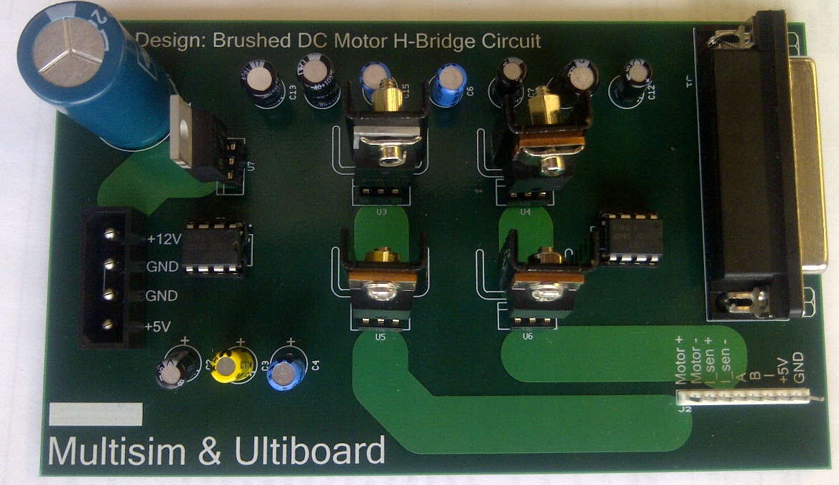
One of the projects that NI Toronto R&D team has been working on for a while, and published a Designcon 2012 paper in, is the system level desktop co-simulation of a brushed DC motor H-bridge control circuit in LabVIEW and Multisim and its implementation using Compact RIO. What I was working on is the prototyping of the analog circuitry on a PCB that interfaces to the Compact RIO platform and carries high current up to 20 A.

The detailed design steps are listed in this tutorial, but what I was really amazed of is that in no more than 6 hours I managed to accomplish the following tasks in Multisim and Ultiboard and my final design was working perfectly from the very first prototyping iteration:

1. Creating the schematic capture of the design

2. Transferring the design to Ultiboard and creating the PCB design including:

     2.1 Creation of 2 component footprints from scratch

     2.2 Manual routing of high current tracks

     2.3 Power planes and board outline definition

     2.4 In-place editing of footprints on an already routed board

3. Generating the Gerber files and sending them out to NI partner, Sunstone Circuits, for fabrication

4. Ordering the components from our partner, Digi-Key

5. Solder the board and test it with the hardware for prototype validation

Below I added some screenshots or the design.

Have a great weekend and enjoy,

Mahmoud

motor1.png

motor 3.jpg

motor_4.jpg

GarretF
14846 Views
0 Comments

This post is part of a series on what's new in Circuit Design Suite 12.0

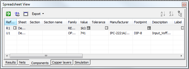
This week's post brings no new functionality - you might even argue that we've hidden some functionality. What is this all about? It's about the buttons in the spreadsheet.

Before:

SpreadSheetBefore.png

After:

SpreadSheetNow.png

By a simple count, there are now 4 fewer buttons, plus, some of the buttons are now on the left. Even the icons have changed! What's going on here?

This improvement for version 12.0 was about focusing on what is important and getting rid of the distractions that keep you from finding what is important (the distractions are now in the Export menu in the spreadsheet).

On the left, you'll find things you can do with the information in the table, and on the right, you'll find things to determine how and what information to show in the table. We don't think every customer will even notice this change, and that's okay. But we do think that you may find the buttons more helpful when your designing now that the most important ones get all the attention.

GarretF
13098 Views
0 Comments

As part of the R&D group, I'm not the one usually announcing new products. That's usually better left for our marketing folk, but today, I'm making an exception.

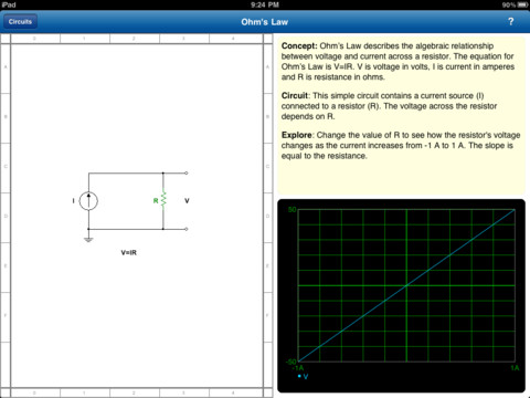
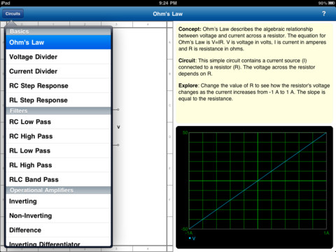
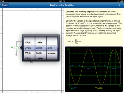
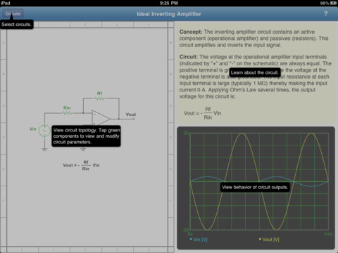
I'm excited to announce Multisim Circuit Explorer for iPads available on the iTunes App Store. Multisim Circuit Explorer is what I call a "textbook companion," and allows students to gain insight into how various elements in a circuit affect the circuit behaviour. The truly innovative and cool part of this product is the immediate feedback. When modifying a component, whether by selecting from a list or sliding a control, the graph updates immediately to show the truly dynamic circuit behaviour.

There are 18 circuits in this release, covering RLC basics, filters, and op-amps.

mainpage.jpgcircuitslist.jpg

editor.jpghelp.jpg

GarretF
11816 Views
0 Comments

This post is part of a series on what's new in Circuit Design Suite 12.0


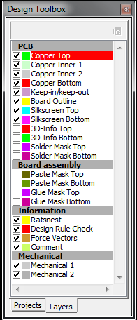
Copper areas and power planes occupy a significant amount of the board real estate. As such, then can cover up other features on the board. You can control the visibility of all objects on a particular layer using the Layers tab in the Design Toolbox. Click the check box to the left and see items on that layer go between visible, dimmed (semi-transparent) and hidden.

LayersTab.png

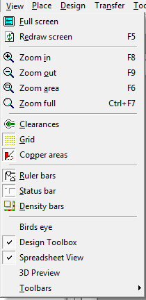
Changing layer visibility doesn't help if the copper areas that were blocking your view is on one of the layers of interest. Ultiboard has another option, buried in the Global preferences on the PCB Design tab: the Show copper areas option. This option is so helpful that I've always wished I could quickly access this through the View menu. In version 12.0, now you can as the Copper areas item! You can even assign it a shortcut key.

ViewCopperAreas.png

GarretF
15108 Views
0 Comments

This post is part of a series on what's new in Circuit Design Suite 12.0

The Circuit Design Suite (Multisim and Ultiboard) applications are serious applications. For students, they provide a means to understand electronics; for professionals, they provide means to design electronics and create products. When we develop these products, we recognize that customers are using them to do work. But can work also be fun?

One of my personal goals is for our customers to smile when they use our products. I mean that quite literally, to actually smile. The idea is from Microsoft, but it really applies for our products too. There are a number of factors that influence whether we can elicit a smile, and they can be hard to quantify. Sometimes you just know when you see it. While I was testing out a small product improvement, I found that smile.

The 3D view in Ultiboard now shows a magnifying glass when zooming. But the developer who gave zooming an icon went a little further. The colour inside the magnifying glass changes depending on what is underneath the cursor. When I first noticed it, I found myself compelled to move the cursor around to see what colour would show up for different parts, traces, etc on the board. It was fun.

To see this effect, open an Ultiboard design. Click Tools > View 3D to show the 3D view (below). Then right click and move your cursor around.

3DView.png

Go ahead and try it for yourself.

Mahmoud_W
19520 Views
0 Comments

Hello Circuit Designers,

The most-feature rich and application-oriented release of NI Multisim and NI Ultiboard is already out and it brings good news to circuit designers in different application areas.

One main application area Multisim 12 addresses is the power electronics field.

For a long time, analog designers developing power electronics and electromechanical circuitry worked separately from digital coders deploying digital logic and FPGA code. The first time these designs met is at the hardware prototype stage were many design inconsistencies are discovered and many prototype re-runs are performed to achieve the desired performance specifications.

Now, with Multisim 12 and LabVIEW 2011, engineers working on power electronics, energy applications, and electromechanical designs can perform accurate desktop point-by-point simulation of their analog and digital designs. An unparalleled design solution by NI Multisim and NI LabVIEW using the newly added co-simulation feature in Multisim 12.

Cosim.jpg

Multisim and LabVIEW system co-simulation capabilities along with the new models added for power electronics components such as PWM controllers, Silicon Controlled Rectifiers, Reconfigurable RLCs and Transformers, and Machine and Motor models help engineers optimize their circuit design performance at the desktop simulation level.

We are very excited about this long awaited feature, and looking forward to hear back about your success story using it so keep circulating your feedback!

Enjoy,

Mahmoud

Getting Started Resources:

Introduction to Digital and Analog Co-simulation Between NI LabVIEW and NI Multisim

Introductory Tutorial Video: Power Electronics Co-Simulation with Multisim and LabVIEW


Additional Resources:

Download Multisim 12.0.0 Professional Edition 30 Day Evaluation

Watch a Webcast on Optimized Circuit Design Using Multisim

GarretF
10674 Views
0 Comments

This post is part of a series on what's new in Circuit Design Suite 12.0

Multisim and Ultiboard now use Windows Vista/7 style dialogs for opening and saving files. That means instead of

OpenFileVersion11.PNG

you now see

OpenFileVersion12.PNG

When I first made the change, I did it thinking the dialogs looked more modern. I didn't recognize how useful the change was until I was comparing Multisim 11 and Multisim 12. I needed to open a file I had downloaded (and hence was in my Downloads folder). I had to browse through several folders to get there in Multisim 11, but in Multisim 12, the link was right there in my Favorites.

Mahmoud_W
15307 Views
0 Comments

Hello Circuit Designer's,

Check out this tutorial written by an engineering manager at Analog Devices talking about his recent experience of using Analog Devices' edition of Multisim component evaluator for the first time.

Cheers,

Mahmoud Wahby

Product Marketing

National Instruments

GarretF
10797 Views
0 Comments

The development team for Circuit Design Suite has been hard at work for quite some time creating and testing version 12.0, which I think is the best release of Circuit Design Suite yet. There are tons of great new features that the marketing and sales teams will be more than happy to tell you about. (Seriously, you should be talking to them now and ask about LabVIEW-Multisim Co-simulation.) But this release is more than great new and improved features. We've also focused on the small details that make Circuit Design Suite a great product.

Check out the new Multisim website for details about version 12.0.

Over the next few months, I'm going to be highlighting the small details that went into version 12.0 (along with a few big ones too). I hope whether you're new to the products or a long time user, you'll find something new and something interesting in this series of posts.

Bhavesh
12366 Views
0 Comments

Hello All,


February 6th 2012 is an exciting day here at National Instruments with the official announcement of Multisim 12.0! The NI team has been working hard for the past 2 years on this major new release and some of the features that are now available are expanding circuit simulation - whether in the domain of circuits education, or circuit design - into new application areas.

It is important that engineers, students and educators are successful when they use NI Multisim, so I would love for you to check out the new features and provide feedback. Some of the exciting new features you will in Multisim 12.0 include:


  1. Multisim Snippets: Now you can place an image (.png) on a webpage, e-mail or any other place, which has a Multisim 12.0 file embedded inside of it. This means you can simply drag-and-drop images directly to Multisim and turn an image into a simulatable circuit (check out more here - http://zone.ni.com/devzone/cda/tut/p/id/13668)
  2. More Power Components: Power applications continue to become more sophisticated. We are working with the world’s leading semiconductor manufacturers to add power devices such as power switches, controllers, transformers and non-ideal RLCs to an existing group of switch-mode-power-supplies from previous editions of Multisim (learn more at - http://zone.ni.com/devzone/cda/tut/p/id/13714)
  3. Analog and Digital Co-Simulation: One of the great difficulties in simulation is being able to accurately simulate analog and digital systems together. For example, if defining a digital controller you will need to interface to analog circuitry (such as the power devices discussed above). Simulating the two of these together has traditionally been difficult (or impossible) with older tools. With Multisim 12.0 you can simulate analog circuitry with embedded code (LabVIEW FPGA) with accurate point-by-point co-simulation. This is a first, and create a new paradigm for teaching power, or designing sophisticated applications (read more at http://zone.ni.com/devzone/cda/tut/p/id/13663)
  4. Design for CompactRIO, Single-Board RIO, DAQ (myDAQ): Defining a connector for your custom designs is difficult (you have to make sure your pin-mappings are correct, spacing is perfect etc...). We have seen engineers take hours (if not days) to make sure a connector is correct - and if not you're looking at wasting weeks in prototype iterations as well as thousands of dollars per prototype run. NI has made it easier and will save you days of work by providing 90+ connectors for NI products like CompactRIO, Single-Board RIO and DAQ devices in Multisim 12.0. Check out the connectors, as well as reference designs to get your work started at http://zone.ni.com/devzone/cda/tut/p/id/13717


This is but a glance of some big (and powerful) new features. Check out the rest at http://www.ni.com/multisim/whatsnew/

Since National Instruments acquired the Multisim product-line in 2005 (wow, 7 years go by quickly!) we have been working to bring new features into a rapidly changing environment - both in academia as well as in industry. During that time our releases have steadily incorporated more innovative features, more simulation capabilities, more usability enhancements, and finally more user requested changes. I continue to be taken aback by how our R&D team is able to incorporate so much into each release! This is when we get to see the true result of these efforts when the engineers of the world begin using these features to become more innovative and productive. I can’t wait to hear your feedback!

If you are ready to download and try out the software for the first time, go to http://www.ni.com/multisim/try/

Thanks for continuing to work with National Instruments. Multisim 12.0 is a big release for us, and we look forward to hearing how you have become more successful with our products!

Bhavesh Mistry

General Manager

National Instruments Toronto

Official News Release: http://digital.ni.com/worldwide/bwcontent.nsf/web/all/531352F15193F4BE8625799C00519211

Bhavesh
11754 Views
0 Comments

Hello All!

The National Instruments Toronto team were excited this year to be able to present an all new paper at DesignCon 2012 entitled "An Improved Co-Simulation Approach to Rapidly Prototype, Verify and Implement Dynamic FPGA-based Embedded Control Systems". The paper was written by two of our simulation engineers here on our R&D team (Oleg and Muris).

Before the session this morning, we were informed that the paper had been nominated as one of the best papers of the conference (a huge honour for the NI Toronto team!) Attendees were impressed by the all new concepts discussed in the paper and an all new approach to analog and digital design is being considered by a new group of engineers here in North California.

The official DesignCon session description:

This session presents a new co-simulation methodology for the rapid prototyping, design, and verification of digital controllers for switching power electronics circuits. A case study of a closed-loop DC motor drive, comprising of a digital controller and analog drive circuitry, is used to illustrate the new method. Using an NI Multisim SPICE simulation plug-in for the LabVIEW simulation module the complete system was verified and optimized using transient simulation prior to being implemented in hardware. All digital FPGA elements were modeled in a graphical system design/programming environment, while the analog power stage was modeled with SPICE. The system simulation results were compared to the experimental measurements. It was found that the measured motor speed and the DC motor armature current closely matched the simulated results, supporting the method of co-simulation as a valuable, insightful and productivity enhancing initial step prior to system implementation. Click for website here.

Interested? But you were unable to attend the show this year? Well we have put the slides up online to share with you. Just click on the PDF below.

There will be more content coming live about co-simulation etc... over the next few weeks, so be ready to learn more! Need to contact someone about it? Message mahmoud.wahby@ni.com.

Thanks,

Bhavesh

Download All
Bhavesh
11711 Views
0 Comments

Hello All,

If you are at DesignCon 2012 this year, please drop by the National Instruments booth (we are located at booth 806 - click here for more details) to learn how you can win a Lego Mindstorms NXT. All you need to do is drop off your information and we'll be making the draw on Wednesday, February 1st 2012.

To learn more about the Lego Mindstorms, check out the link here: http://shop.lego.com/en-CA/LEGO-MINDSTORMS-NXT-2-0-8547. Powered by a 32 bit processor, it includes sensors, servo motors and the ability to be programmed easily in LabVIEW.

While at the booth, make sure to learn all about NI Multisim, NI LabVIEW, NI Single-Board RIO, NI CompactRIO and PXI!


See you all there,

Bhavesh

Untitled.jpg

Bhavesh
11898 Views
0 Comments

Hello All,

It's that time of year again as we make our way to the Santa Clara Convention Center for DesignCon 2012. We are excited by this years show as we bring together some great demos, a fantastic paper presentation, a panel discussion as well as a give-away for anyone that stops by the booth. We're located at booth 806 (Click here for more details).

  1. Check out the session entitled "An Improved Co-Simulation Approach to Rapidly Prototype Verify and Implement Dynamic FPGA-Controlled Systems" with Oleg Stepanov and Muris Mujagic of the NI Toronto team. Be there in Ballroom C on Wednesday 9:20 am to learn about some cutting-edge new technology from National Instruments for design, prototyping and co-simulation. Check out the session details here.
  2. Eric Starkloff (National Instruments VP of Test and Industrial Embedded) will be a part of a panel discussion entitled "Delivering On Time-To-Answer: Meeting Designers Needs in Test and Measurement" along with other leaders in test and measurement. Be sure to check it ou on Wednesday at 3:45pm at the theater. Check out the panel details here.
  3. Mahmoud Wahby and Fernando Dominguez (Product Managers for NI Multisim) have put together 4 great demos for the show - including two showing off a brand new co-simulation approach that many of you have never seen before! Come speak to any of us to see how it will change the way you prototype your designs. If you want to learn more you will have to be there! (feel free to message me at bhavesh.mistry@ni.com if you want to pointed to some great content!)
  4. We will be having a give-away this year - but you MUST stop by the National Instruments booth to enter. With any luck you will be the lucky person walking away with either gift cards, or our bigger prize - guaranteed to be a must for any budding engineers you have in your family. Stay tuned for more information!

We will see you all there today (January 31st) to February 1st!

Thanks!
Bhavesh

MahtabZ
45569 Views
0 Comments

     Did you know that you can change the look and feel of your Multisim workspace? Multisim is highly customizable, and allows you to change almost anything about the environment you’re working in.

     To learn how to tailor your workspace to your taste, watch these two videos. The first will teach you how to change Global Preferences, and the second will teach you how to change Sheet Properties.

Below, I have provided an overview of the main points of the videos.

Global Preferences


These preferences are common to every project you will be working on with your computer.

            To change your Global Preferences, from the toolbar go to Options » Global Preferences.

            From Global Preferences, you can change aspects of your work environment. These include the location of the Master, Corporate, and User databases and User Configuration File, what action to take once a part has been placed, mouse wheel behavior, wiring options, and language.

Sheet Properties


Sheet Properties only affect the current file you are working on. These preferences are saved with the circuit file so that if the circuit is opened on another computer, you will see the same thing.

To change the Sheet Properties, from the toolbar go to Options » Sheet Properties.

From here you can decide which attributes of the components, connectors, net names, and bus entries will be shown on the circuit. You can modify the colour scheme, whether or not to show a grid or border on the page, and wire width and bus width.

Now that you know how to modify the Global Preferences and Sheet Properties, you will find that designing a circuit in Multisim becomes faster, and this will make you more productive!

MahtabZ
19536 Views
1 Comment
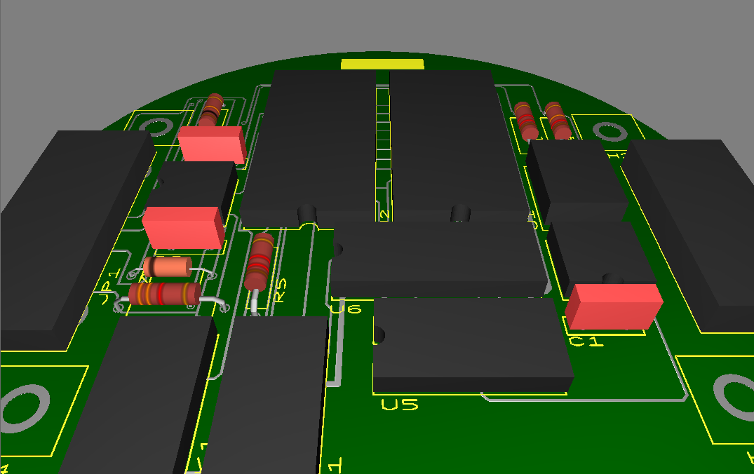
Last week, I talked about how to view your PCB design in 3D. This week, I’ll deal with a bit of a tougher question – what happens if you create your own footprint in Ultiboard, and the part doesn’t have any 3D information associated with it?

Like I said last week, being able to see a PCB in 3D provides an intuitive way of viewing your design. In Ultiboard, adding 3D information to a footprint is easy, and it's a good idea to do this whenever possible. So let’s get started!

First, open Ultiboard and find the part you’d like to edit. If you haven’t created a footprint, but would just like to edit the 3D information of an existing component, you can copy a component from the Ultiboard Master Database into your own User Database.
1. From the toolbar, go to Tools » Database » Database Manager.

2. Find the footprint that you would like to add 3D information to, and click the edit icon, as shown in Figure 1.
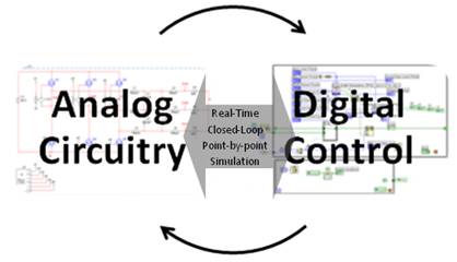
Figure 1.PNG

Figure 1: Selecting a part to edit


3. You are now in Footprint edit mode. In the Design Toolbox, switch to the Layers tab, shown in Figure 2.

Figure 2.PNG

Figure 2: The Layers tab of the Design Toolbox

4. Double-click the 3D-Info Top layer to make it the active layer. It should be highlighted red to indicate that it is now the active layer.

5. If you’re simply modifying the 3D information for an existing part, move on to step 6. Otherwise, if you’re adding 3D information for a new footprint you created, select Place » Shape and select the shape you want for your component, such as a circle or rectangle. Place it directly over the silkscreen of the object.

6. From the toolbar, go to Edit » Properties. This will open the Components and Sheet Properties window.

7. In the 3D data tab, make sure the Enable 3D for this object and the Use 2D data to create 3D shape checkboxes are both selected, as shown in Figure 3.

Figure 3.PNG

Figure 3: 3D data tab of the Part and sheet properties window

8. From here, you can change 3D settings for this part. Look under each of the sub-tabs (General, Material, Pins, and Cylinder) for more options.  Anything you change will be automatically visible in the Preview area on the right of the window.

Adding 3D information for parts in Ultiboard is relatively simple, and can help you visualize what a board will look like when manufactured.