- Document History
- Subscribe to RSS Feed
- Mark as New
- Mark as Read
- Bookmark
- Subscribe
- Printer Friendly Page
- Report to a Moderator
- Subscribe to RSS Feed
- Mark as New
- Mark as Read
- Bookmark
- Subscribe
- Printer Friendly Page
- Report to a Moderator
NI VeriStand FPGA-Based I/O Interface Tools
![]()
Introduction
NI VeriStand ships with default I/O personalities for a variety of FPGAs. In order to create a custom I/O personality, it’s necessary to start with one of the templates that have the framework already laid out. This document contains an installation for additional NI VeriStand FPGA Support. It installs the NI VeriStand FPGA Clock Support library discussed within the Timing Engine section in Creating FPGA-Based I/O Personalities for NI VeriStand above as well as an NI VeriStand RIO Library and NI VeriStand Custom FPGA Project Wizard discussed below. Before continuing, please install the NI VeriStand FPGA Support installer.
Requirements
- NI VeriStand 2010 or later
- LabVIEW 2010 or later
- LabVIEW FPGA 2010 or later
- NI-RIO
- NI VeriStand FPGA Support (installer attached below)
NI VeriStand Custom FPGA Project Wizard
To begin creating a custom I/O personality, first run the NI VeriStand Custom FPGA Project Wizard. The Project Wizard is accessible from LabVIEW 2012+'s create project dialog under templates (Figure 1). In LabVIEW 2011 and earlier find it in, LabVIEW’s Getting Started window (Figure 2) under Targets. You can always find it by selecting File>>New… and choosing NI VeriStand Custom FPGA Project (Figure 3).
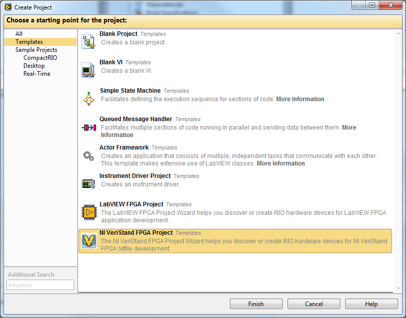
Figure 1. LabVIEW 2012+ Project Template
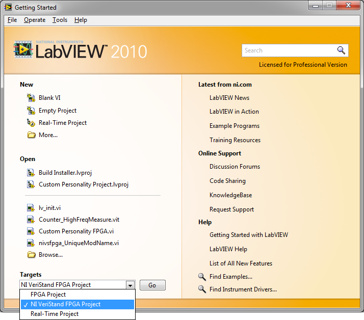
Figure 2. Getting Started Window in LabVIEW 2011 and earlier
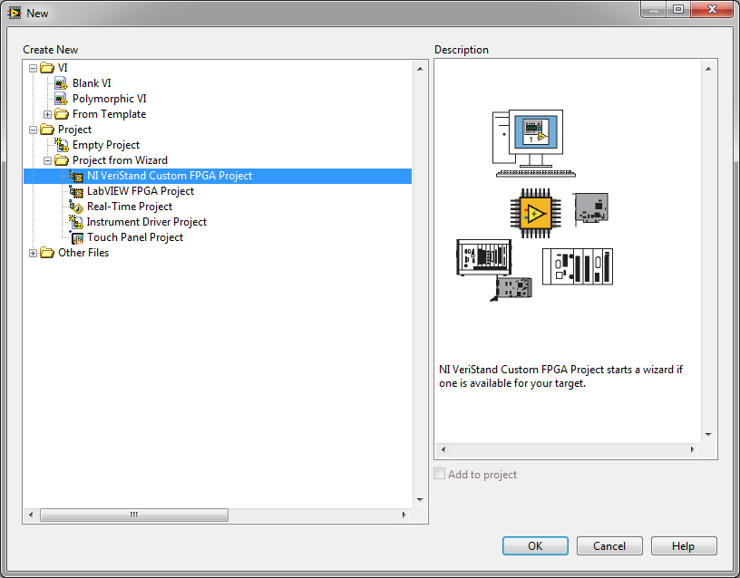
Figure 3. New File Selection in LabVIEW
The NI VeriStand Custom FPGA Project Wizard guides one through the process of selecting the FPGA and any C-Series modules that may be contained within a cRIO or C-Series Exapansion Chassis. It operates similar to the wizard for starting a new LabVIEW FPGA Project except that it adds the necessary components to the project for a custom FPGA to be used with NI VeriStand. The project wizard adds a framework template, DMA FIFOs, and corresponding XML file to begin development. It also saves the project and files to a location specified by the user. A typical project created from the NI VeriStand Custom FPGA Project Wizard is shown in Figure 4.
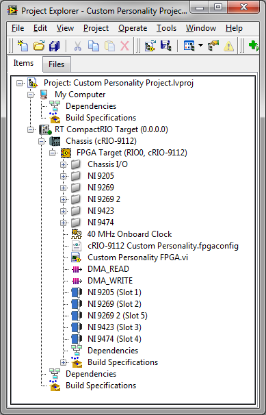
Figure 4. Project created by NI VeriStand Custom FPGA Project Wizard
Framework Template
The project wizard creates an FPGA VI in the project which is generated from a template. There are different templates for PCI, PXI, and cRIO. Both the PCI and PXI templates define the following FPGA I/O items: analog I/O on connector 0, digital lines on connector 1 acting as digital input, digital lines on connector 2 acting as digital output, and digital lines on connector 0 acting as PWM I/O. Note that if a 781xR FPGA is used, it will not have any analog I/O and will have extra digital I/O. If an R-Series Expansion Chassis is used on either connector 0 or connector 1, the digital I/O for the corresponding connector will need to be removed. The cRIO template defines I/O for NI 9215, NI 9263, NI 9411, and NI 9474 modules. The project wizard does not modify the templates according to the I/O discovered. It is the responsibility of the developer to modify the FPGA VI to match any changes in I/O from those listed above.
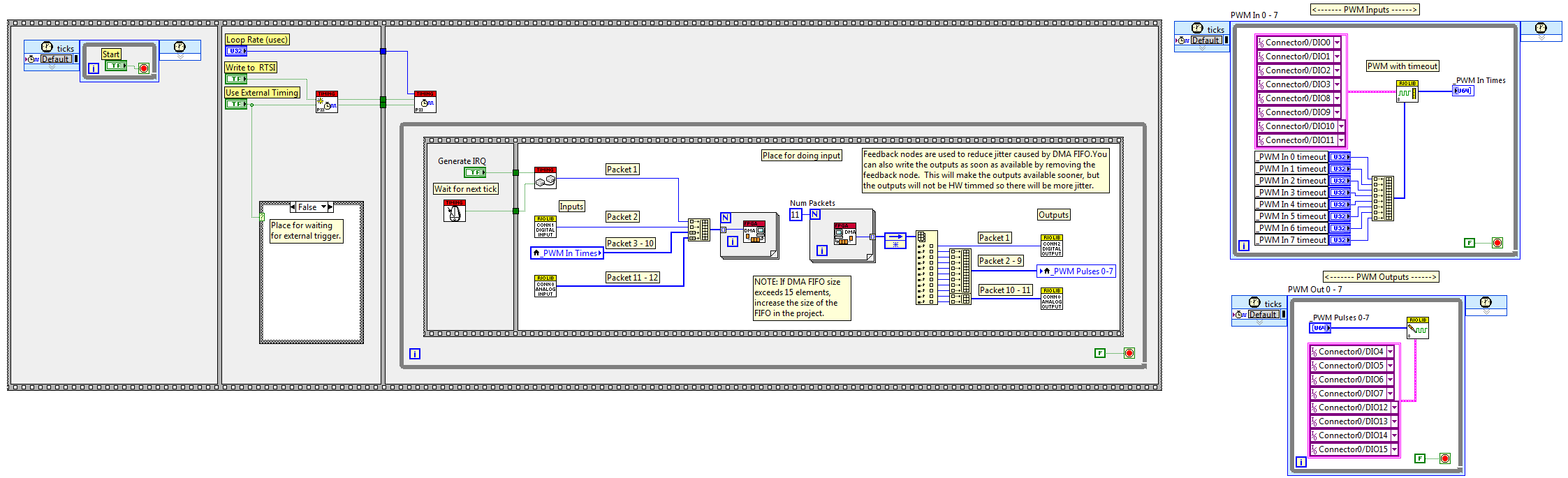
Figure 5. FPGA VI PXI Template
The templates are only meant to be modified by adding or removing I/O in the main frame of the communication loop and by adding or removing asynchronous loops outside of the main sequence structure. The templates have been designed so that a user should not edit anything that has a gray background or remove any of the subVIs that have a red background in the title.
The FPGA template can be customized by adding basic I/O to the communication loop. When adding inputs, convert the data to U64 packets, expand the build array, and connect the U64 packets to the build array.
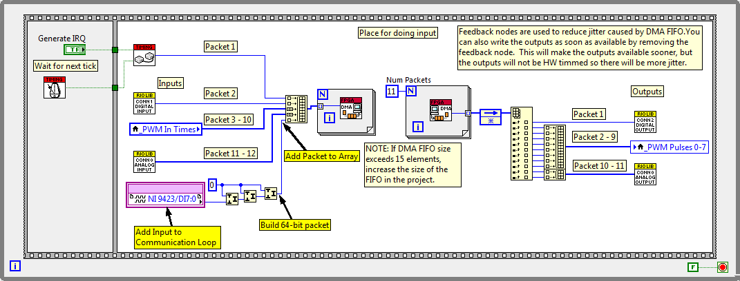
Figure 6. Adding Inputs to Communication Loop
When adding outputs, first increment the “Num Packets” constant wired to the count terminal of the For loop to account for the additional packets needed by the additional outputs. Next, expand the index array function to give access to the additional packets returned by the For loop. Then connect these packets to the added outputs. If the outputs require more than one packet, build an array from the packets required and connect the array of packets to the outputs.
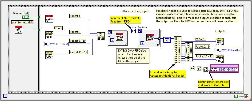
Figure 7. Adding Outputs to Communication Loop
When adding asynchronous loops to perform any type of processing asynchronous to VeriStand’s communication loop, create the asynchronous loop, convert any data sent to or from the loop to U64 packets, and then connect the packets between the asynchronous and communication loops via local variables. Connect the local variables in the communication loop to the DMA FIFOs by following the steps for inputs or outputs above.

Figure 8. Connecting Asynchronous Data to Communication Loop
Adding basic I/O to the communication loop and IP based I/O in asynchronous loops is made easier with the NI VeriStand RIO Library contained in the installation attached to this document.
NI VeriStand RIO Library
After installing the NI VeriStand FPGA Support, NI VeriStand RIO Library will appear on the FPGA function’s palette.
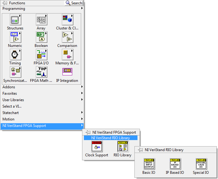
Figure 9. NI VeriStand RIO Library Palette
The NI VeriStand RIO Library was created so that creating a custom FPGA bitfile for NI VeriStand will be less cumbersome and not require LabVIEW FPGA expertise. Each C-Series module with the exception of communication modules (CAN, Profibus, etc.), motion modules, removable storage modules, and third-party modules has been included in the NI VeriStand RIO Library. The modules are separated between Basic I/O and Special Case I/O.
Basic I/O consists of any C-Series module whose I/O can be placed directly in the communication loop. Customizing the FPGA VI with basic I/O only requires dropping the corresponding subVI in the communication loop, creating a constant that defines the I/O being used by the subVI, and connecting the packet input or output of the subVI to the corresponding packet receive or packet send For loop.
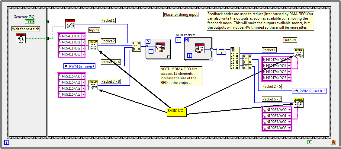
Figure 10. RIO Library's Basic I/O
Special Case I/O consists of C-Series modules that either use a Delta-Sigma ADC and are independently timed (such as the 9233) or consist of high resolution ADCs that execute too slow to place in the communication loop (such as the 9211). The special case I/O subVIs are meant to be placed on the block diagram as asynchronous loops. When placing the special case I/O subVI on the block diagram, its contents will be placed instead of a subVI. The contents will consist of the asynchronous loop and packet indicator. Finish by creating a local variable for the packet and placing it into the communication loop to connect to the DMA FIFO.
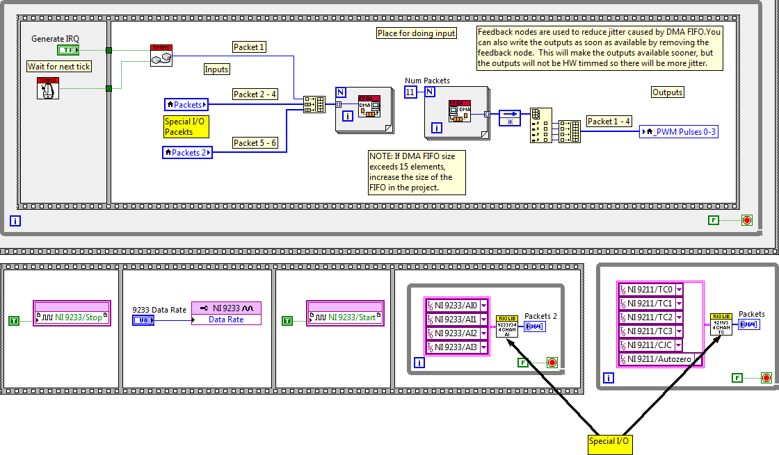
Figure 11. RIO Library's Special I/O
Some loops require additional processing instead of simple I/O connectivity. One example is PWM and frequency measurements. The NI VeriStand RIO Library also contains IP (Intellectual Property) Based I/O that will allow the user to quickly take advantage of the power of the FPGA with an asynchronous loop already programmed to perform a specific function. The IP Based I/O will be implemented as asynchronous loops in the same manner that Special Case I/O is implemented.
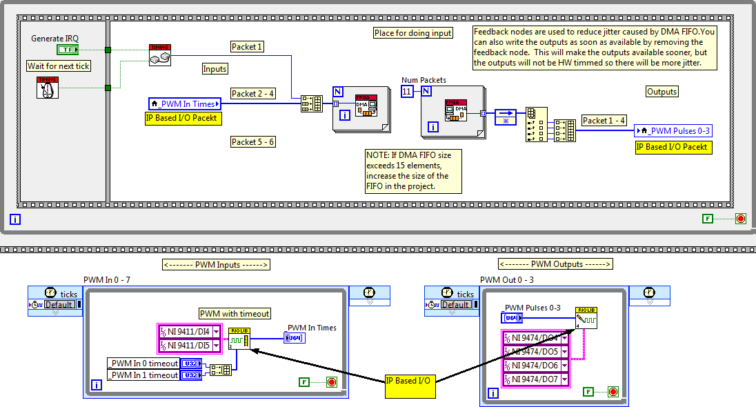
Figure 12. RIO Library's IP Based I/O
The IP Based I/O palette consists of PWM or Pulse Generation/Measurement, Encoder Input, and Quad Encoder Input. Additional IP Based I/O may be added in the future and can also be created by any user. If you create any additional IP Based I/O and wish to include it in a future release of the NI VeriStand RIO Library please comment below.
The final step to creating a custom FPGA personality for NI VeriStand is defining in XML the data sent to and from the FPGA in the 64-bit packets. Please refer to the NI VeriStand Help for the topic on Creating a Custom FPGA Configuration File.
The NI VeriStand RIO Library includes an XML snippet in each subVI that defines the data in the packets received/generated by the subVI. This snippet can be copied and pasted into the corresponding section of the *.fpgaconfig file that defines the interface from FPGA to NI VeriStand host.
Special considerations for multiple Non-R Series RIO targets
If you are using multiple RIO targets (that do not have PXI timing and synchronization features like R-Series), you must take synchronization into consideration. For example, if you are using two MXIe RIO targets with a Real-Time PXI... the system performance will greatly suffer unless you synchronize the two MXIe RIO targets.
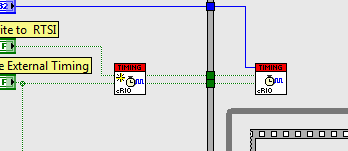
The framework provided by this add-on has built in synchronization support to accomplish this. It uses a 9401 or 9402 module to share a distributed clock between the RIO targets. This is disabled by default and must be enabled by the user. To enable this functionality:
- Verify that your FPGA personality is using the cRIO sync VIs and not the PXI ones. You can do this by looking to see that they have the "cRIO" text on their subVI icon:
- Add a 9402 or 9401 module to each chassis. 9402 is preferred because its higher signal integrity and ease of connectivity (BNC)
- Right click the FPGA target and go to properties
- Select conditional disable symbols and add a new symbol named "FPGA_RTSI_SYNCH" with the value of either "9402" or "9401" depending on which module you used
- Connect the DIO0 line of the 9402 or 9401 modules on each RIO target you wish to synchronize
Known Issues
- The pulse input and output allow selection of PWM IP however this IP is so limited it is rarely useful and often misleading. It only allows variation of duty cycle at run time, period is a fixed value setup in the system explorer. Instead, we should replace or supplement the IP selection to include NIVS PWM IP that allows selection of duty cycle and frequency at run time.
Release Version History
1.3.0
- Added modules (multiplexer, resistive output, fault injection) from Wireflow under the Special IO -> HIL palette
- Added 9220 support
1.2.0
- Fixed a serious problem preventing Chinese language users from using the wizard
- Added support for LV 2012 and later
1.1.2
- The XML for the 9213 and 9217 have been corrected to include the missing </Parameters> tag
1.1.1
- The XML for the 9265 had the wrong combination of FXP integer word length and scaling. This has been fixed.
1.1
- the subVI for the 9227 and the 9239 (one subVI for both modules) now has two XML comments... one for each module. use the one you need.
- the subVI for the 9233 and the 9234 (one subVI for both modules) now has two XML comments... one for each module. use the one you need.
- the subVI for the 9235, 9236 and the 9237 (one subVI for three modules) now has three XML comments... one for each module. use the one you need.
- Units for the 9235, 9236, and 9237 module have been corrected to be V/V instead of Volts
- the XML for the 9235, 9236, and 9237 has been modified to work around bug report #258756 that caused incorrect data on VXWorks. This bug was fixed in NI Veristand 2011, but the XML will now work with all versions of NI VeriStand.
- the 9208 xml now says 9208 instead of 9207
- the XML for the 9208 has been modified to work around bug report #258756 that caused incorrect data on VXWorks. This bug was fixed in NI Veristand 2011, but the XML will now work with all versions of NI VeriStand.
- the XML for the 9211 and 9213 has been modified to work around bug report #258756 that caused incorrect data on VXWorks. This bug was fixed in NI Veristand 2011, but the XML will now work with all versions of NI VeriStand.
- the subVI for the 4 chan 9111 and the 9213 (one subVI for both modules) now has two XML comments... one for each module. use the one you need.
- Units for the 9217 module has been corrected to be Ohms instead of Volts
- added the ability to set the conversion time for the 9217
- added the ability to set the conversion time for the 9213 (the FPGA code was there but the control was named wrong and the XML didn't support writing to the control)
- added the ability to set the conversion time for the 9219 (the FPGA code was there but the control was named wrong and the XML didn't support writing to the control)
- the XML for the 9219 has been modified to work around bug report #258756 that caused incorrect data on VXWorks. This bug was fixed in NI Veristand 2011, but the XML will now work with all versions of NI VeriStand.
- Units for the 9219 module has been corrected. Channel 3 was volts and should have been volts per volt.
- Corrected the 9201 module to work. There were multiple problems causing this module to not work at all.
- the XML for the 9203 has been modified to work around bug report #258756 that caused incorrect data on VXWorks. This bug was fixed in NI Veristand 2011, but the XML will now work with all versions of NI VeriStand.
- Units for the 9203 module has been corrected to be Amps instead of Volts
- Corrected the 9221 module to work. There were multiple problems causing this module to not work at all.
- Units for the 9265 module has been corrected to be Amps instead of Volts
- Fixed a typo in the description of the 9265 module xml
- the XML for the 9265 has been modified to work around bug report #258756 that caused incorrect data on VXWorks. This bug was fixed in NI Veristand 2011, but the XML will now work with all versions of NI VeriStand.
- 1 channel pulse measurement has been corrected to have correctly named control for timeout
- corrected the pulse measurement VIs (1,2,4, and 8 chan) to have XML that correctly names the timeout parameter
- corrected templates to have correct parameter name for PWMs
Integration into NI VeriStand
- Customize the FPGA VI generated by the NI VeriStand Custom FPGA Project Wizard.
- Compile the FPGA VI to generate the bitfile (.lvbitx).
- Modify the FPGA Config XML file (.fpgaconfig) to match the packet definition in the FPGA VI (RIO Library VIs have the XML on their block diagram).
- Copy the bitfile, config file, and schema (.xsd) in to either your NI VeriStand project directory or into the globally available Public Documents\National Instruments\<NI VeriStand Version>\FPGA directory.
- Add the FPGA personality to an NI VeriStand System Definition.
Additional Resources
- View the Creating FPGA-Based I/O Personalities for NI VeriStand online tutorial
- View the online documentation for NI VeriStand FPGA Personalities
- Watch NI VeriStand demonstration videos
Support and Contact
This software is not yet officially supported by National Instruments. If you encounter a problem with these tools, or if you have suggestions for a future revision, please post to the forum for this tool: NI VeriStand FPGA-Based I/O Interface Tools Discussion. You must use this feedback forum for support. Do not call National Instruments for support for this add-on.
National Instruments does not support this code or guarantee its quality in any way. THIS SOFTWARE IS PROVIDED "AS IS" WITHOUT WARRANTY OF ANY KIND AND SUBJECT TO CERTAIN RESTRICTIONS AS MORE SPECIFICALLY SET FORTH IN NI.COM'S TERMS OF USE (http://ni.com/legal/termsofuse/unitedstates/us/).
- Mark as Read
- Mark as New
- Bookmark
- Permalink
- Report to a Moderator
Fails to install in 2013, and I don't see an explanation of how to manually install the files.
- Mark as Read
- Mark as New
- Bookmark
- Permalink
- Report to a Moderator
Hello!
I have it installed on 2013 so something must be going wrong on your machine. Are you running LabVIEW as administrator when you run the installer VI? This is required.
Also, I've noticed some people have trouble with long path names. You might want to unzip the contents (be sure to unzip before running the installer) to a short path like C:\temp
- Mark as Read
- Mark as New
- Bookmark
- Permalink
- Report to a Moderator
I was running as admin. The file path length was the issue. I was getting a 'generic file I/O error' prior. Now the install completed once I shortened the path.
But after I restarted LabView and I run the 'NI VeriStand FPGA Project" template I get the following error:
Unable to load FPGA Project Wizard
Possible causes:
- LabVIEW FPGA is not installed.
- The LabVIEW FPGA installation is corrupt.
I definitely have the FPGA madule installed and it is not corrupt as I have been using it daily with no other issues.

Any help is appreciated.
- Mark as Read
- Mark as New
- Bookmark
- Permalink
- Report to a Moderator
Well... at least we are making some progress.
What happens if you try to start the LabVIEW FPGA Project template? (The NIVS template hooks into this one)
- Mark as Read
- Mark as New
- Bookmark
- Permalink
- Report to a Moderator
The LabVIEW FPGA Project template works just fine.
- Mark as Read
- Mark as New
- Bookmark
- Permalink
- Report to a Moderator
Great!
No, EtherCAT does not use DMA and uses a totally different interface. See the scan engine custom device page to learn how to use that with NI VeriStand: NI VeriStand Add-On - Scan Engine and EtherCAT
- Mark as Read
- Mark as New
- Bookmark
- Permalink
- Report to a Moderator
What if when i genereate the FPGA project for sbRio or cRio and then click on the FPGA project it asks me for FPGA PWM In/OUT and
Receive Packet From Host.vi
Send Packet to Host.vi.
How do I find these?
- Mark as Read
- Mark as New
- Bookmark
- Permalink
- Report to a Moderator
Hi wegunterjr
Whwen you are installing versinatd you need to install support for LabVIEW. As well as you need LabVIEW FPGA module installed.
Applications Engineer
National Instruments
- Mark as Read
- Mark as New
- Bookmark
- Permalink
- Report to a Moderator
The code works well and helped me a lot. Thank you!
I did have 2 issues with the QuadEncoder Position Velocity.vi:
1) the XML code snippet given in the VI block diagram uses U32 for Position, Velocity, Acceleration. This works well when the encoder is rotaing in +ve direction, but causes rollover when encoder reverses direction. I changed the XML code to I32 for Position, Velocity, Acceleration. It then worked ok.
2) If a Z-pulse (0 degree sensor) is connected, then the position is reset to 0 whenever Z-pulse is high. This is expected behavior. But the Velocity becomes a large -ve number once per revolution due to the reset of position to 0. To handle Z pulse correctly, the Velocity Calculation should be ignored when Z-pulse is high.
LabVIEW Developer since Version 2.0
- Mark as Read
- Mark as New
- Bookmark
- Permalink
- Report to a Moderator
Hello, if I create a Custom VeriStand FPGA Project there es no syncronization/timing like in the template C:\Users\Public\Documents\National Instruments\NI VeriStand 2016\FPGA, see pictures:
Custom VeriStand FPGA:


C:\Users\Public\Documents\National Instruments\NI VeriStand 2016\FPGA\Template:

- Mark as Read
- Mark as New
- Bookmark
- Permalink
- Report to a Moderator
hi Rokot,
I am Efeel from china.Are you still update the toolkit?
I want to develop a HIL system with PXIe-7868R,but the Toolkit seems not support the device ,I hope you can give me some helping .
thanks .
- Mark as Read
- Mark as New
- Bookmark
- Permalink
- Report to a Moderator
Hi Efeel,
The tool does not have to support a specific FPGA. You can use a different configuration and modify it specifically for your device.
Here is an example on how to do it for the myRIO:
FPGA Configuration file to use myRIO with VeriStand .
