- Subscribe to RSS Feed
- Mark Topic as New
- Mark Topic as Read
- Float this Topic for Current User
- Bookmark
- Subscribe
- Mute
- Printer Friendly Page
TTL freq measurement w/ variable trigger level
01-09-2008 12:52 AM
- Mark as New
- Bookmark
- Subscribe
- Mute
- Subscribe to RSS Feed
- Permalink
- Report to a Moderator
01-10-2008 01:34 PM - edited 01-10-2008 01:36 PM
- Mark as New
- Bookmark
- Subscribe
- Mute
- Subscribe to RSS Feed
- Permalink
- Report to a Moderator
Hi mlang,
Your way of getting around the blurb in your TTL signal is quite clever. M-series cards like your 6221 do accept analog triggers. However, the string input for the trigger function is picky and will return errors if the correct format is not entered. For the string input, instead of 0, you would want to enter Dev2/ai0.
The Counter Source Inputs are, by default settings, where you would physically connect the signal you want to find the frequency of. However, by using a DAQmx Channel Property Node, we can find the frequency of any digital line we want. When you place down the property node, you can select the input terminal that the frequency measurement will be taken on as seen in the following screenshot.

I am attaching a modified example program that I believe will perform the retriggering analog input and the frequency measurement of the AI Start Trigger. In this example, my M-series card is named “M-series” instead of “Dev2” and my TTL signal is wired to ai1 instead of ai0. I hope this helps and good luck on your transition from Traditional DAQ to DAQmx. I find DAQmx a lot easier to use once you become familiar with the flow of the programs.
Mallori M.
Message Edited by mallorim on 01-10-2008 01:36 PM
01-10-2008 11:34 PM
- Mark as New
- Bookmark
- Subscribe
- Mute
- Subscribe to RSS Feed
- Permalink
- Report to a Moderator
It seems to me there should be at least one example (that works) of analog input where the trigger is a threshold on that analog input (that's what the examples I remember used to be of). But the majority of examples I find either have a very similar flow to your program using the analog trigger and throw that -200077 error (as for the Acq&Graph Voltage-Int Clk-Analog Start w Hyst example), or they use digital lines as a trigger for acquisition. Any reason why I wouldn't be able to select analog trigger for an analog input task?
01-14-2008 12:15 PM
- Mark as New
- Bookmark
- Subscribe
- Mute
- Subscribe to RSS Feed
- Permalink
- Report to a Moderator
Hi mlang,
I want to apologize. While I used an M-series card in my example, after looking at the specifications of your PCI-6221, you are correct that this card does not support analog triggering.
Can I ask if you recently changed cards, or did your PCI-6221 work in your Traditional DAQ application?
Also, can you give me a better description of your TTL signal and the blurb that is causing the difficulties? Does the blurb occur once or is it recurring? If it only occurs once at the beginning of the TTL signal, then you can just perform the regular counter input frequency task and then throw out the first frequency measurement from the data array. The rest of the measurements should be correct.
My other suggestions include finding a way to attenuate the signal so that the blurb was below 0.8 V but the TTL signal was above 2 V. Also, you can look at purchasing a PCI-625x M-series card that supports analog triggering, which is the card I used with the example, or a PCI-654x High Speed DIO card that is expensive but it lets you configure what is considered high and low.
Regards, Mallori M.01-14-2008 12:40 PM
- Mark as New
- Bookmark
- Subscribe
- Mute
- Subscribe to RSS Feed
- Permalink
- Report to a Moderator
01-15-2008 04:43 PM - edited 01-15-2008 04:44 PM
- Mark as New
- Bookmark
- Subscribe
- Mute
- Subscribe to RSS Feed
- Permalink
- Report to a Moderator
Hi mlang,
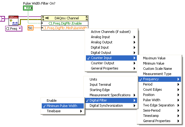
Something you might want to consider is, if the ringing is guaranteed to have a smaller pulse width than the motor pulse, then you can use a counter task with the channel property node of Minimum Pulse Width. This can be seen in the following image.
With each rising edge of the signal, the timebase will begin counting, and if the signal drops off before a certain amount of time has passed, that portion of the signal is discarded. Only pulses of a certain duration are passed on to have the frequency measurement taken. However, this will only be effective if your TTL signal has a longer duration then the ringing noise you are seeing.
Other than this, I would suggest finding the cause of the noise and trying to reduce that. Everything we have previously discussed is more of a bandage, instead of addressing the root problem.
Hope this helps, Mallori M.
Message Edited by mallorim on 01-15-2008 04:44 PM
