Description:
The FPGA VI emergencyLog.vi measures the onboard accelerometers of the myRIO. It shall demonstrate the functionality of a black box inside of a plane.
On the FPGA, the current values of the accelerometers are buffered in a memory block of chunks of 1024 data points per dimension.
If a threshold is exceeded (because an IMPACT occurred) the data will be written into a DMA-FIFO, to be read in the RT VI emergencyLogToUSB.vi. The data is sent via DMA-FIFO to RT VI emergencyLogToUSB.vi in order to write the data to USB, which is not possible on the FPGA. The data could also be written to the flash drive of the NI myRIO, but USB stick is more convenient. 
Exceeded thresholds will also be indicated with the LEDs on the myRIO!
So this VI shows a possible usage of Memory Blocks on the FPGA and how to communicate large sets of data from FPGA to RT without dataloss!
Instructions on how to use Code:
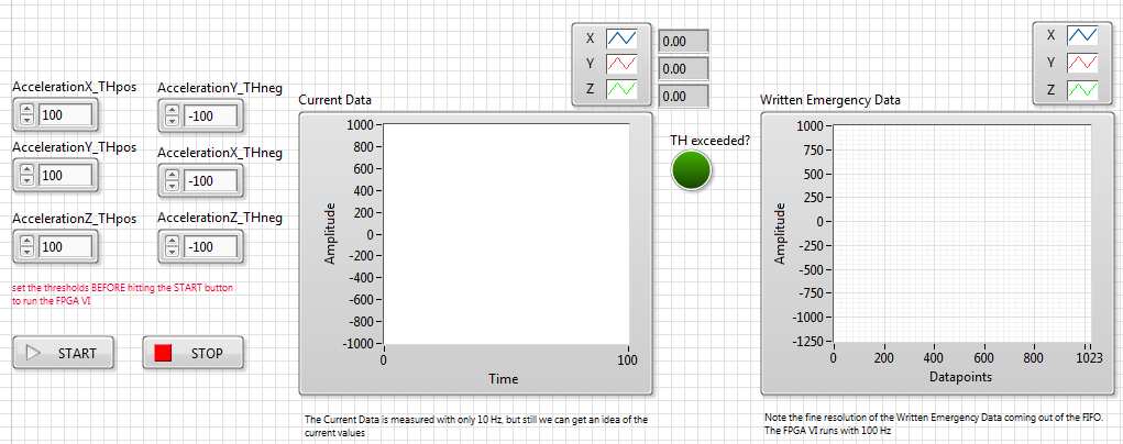
To start this example, open emergencyLog.vi on the RT. After setting up the thresholds on the left, you can hit the START Button. The VI then will call the FPGA VI, which actually does the measuring.
The RT VI emergencyLog.vi is checking the amount of data inside the DMA FIFO, whenever the FIFO is full of the expected amount of data, it writes the data to the USB stick and stops the VI
The FPGA VI stores currently measured points in Memory Blocks, which are used as ring buffers. Once a thresholds is exceeded, the content if the ring buffer will be written into the DMA FIFO.
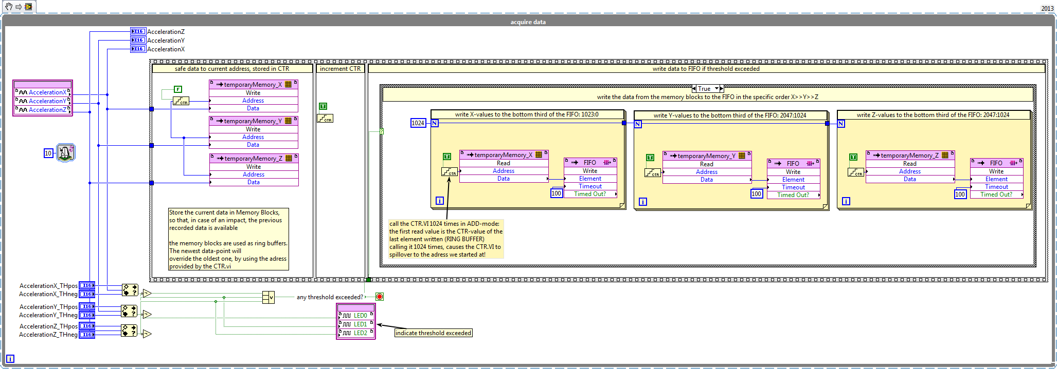
this snippet does not contain the whole FPGA code!!!
Have a closer look at the actual VIs to get an idea of how the project works!
The project does not use any pins from the connectors A, B or C. Therefore the shipped FPGA personality is not used at all!
Feel free to play around with the sampling rates on the FPGA and RT! Or try to add more data (maybe analog inputs etc.). If you want to save webcam pictues as well, refer to the RT-architecture of the alarm clock!
Sunaina K.
Product Marketing Manager for CompactRIO & TSN
Making the intangible, tangible
