- Document History
- Subscribe to RSS Feed
- Mark as New
- Mark as Read
- Bookmark
- Subscribe
- Printer Friendly Page
- Report to a Moderator
- Subscribe to RSS Feed
- Mark as New
- Mark as Read
- Bookmark
- Subscribe
- Printer Friendly Page
- Report to a Moderator
By Rick Weiss & Stephanie Campbell
As one of the first bigger projects on the myRIO, this demo was presented on the NI Week 2013.
It uses LEDs, 7-Segment displays, a ,knob, a PCB mount speaker and onboard hardware like the accelerometers and the onboard button!
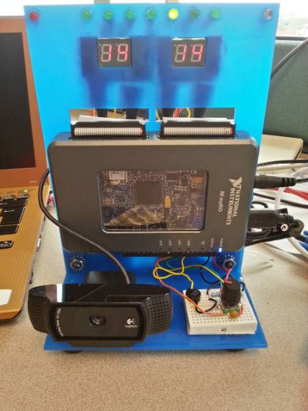
Hardware Usage
For wiring diagrams for each component, check out the Project Essentials Guide!
7 LEDs show the current day (starting with Sunday, Monday, ... , Friday, Saturday)
2 LEDs on the left and right upper corner are used for an intruder alert
2 double-7-segment displays show the time in hours and minutes (military format)
1 usb webcam will survey the room for intruders, when the user left his room
1 knob can be used to edit time and the alarms
1 speaker is used to ring an alarm
3 accellereometers measure user inputs like taps and shakes
1 onboard button is used to switch through the different display modes (clock -> alarm 1 -> alarm 2)
Pinout
Connector A
Pin | Device | Function |
5V | 7SEG_MINs | VCC |
GND | 7SEG_MINs | GND |
DIO15 | 7SEG_MINs | CAT |
DIO14 | 7SEG_MINs | AG |
DIO13 | 7SEG_MINs | AF |
DIO12 | 7SEG_MINs | AE |
DIO03 | 7SEG_MINs | AD |
DIO02 | 7SEG_MINs | AC |
DIO01 | 7SEG_MINs | AB |
DIO00 | 7SEG_MINs | AA |
DIO08 | Surv_LED_BLUE | VCC |
DIO04 | LED_WED | VCC |
DIO05 | LED_THU | VCC |
DIO06 | LED_FRI | VCC |
DIO07 | LED_SAT | VCC |
Connector B
Pin | Device | Function |
5V | 7SEG_HOURSs | VCC |
GND | 7SEG_HOURSs | GND |
DIO15 | 7SEG_HOURSs | CAT |
DIO14 | 7SEG_HOURSs | AG |
DIO13 | 7SEG_HOURSs | AF |
DIO12 | 7SEG_HOURSs | AE |
DIO07 | 7SEG_HOURSs | AD |
DIO06 | 7SEG_HOURSs | AC |
DIO05 | 7SEG_HOURSs | AB |
DIO04 | 7SEG_HOURSs | AA |
DIO08 | Surv_LED_RED | VCC |
DIO09 | LED_SUN | VCC |
DIO10 | LED_MON | VCC |
DIO11 | LED_TUE | VCC |
Connector C
Pin | Device | Function |
GND | Speaker | MINUS |
DIO03 | Speaker | PLUS |
DIO00 | KNOB | Button |
DIO01 | KNOB | A |
DIO02 | KNOB | B |
Functionality
In general the FPGA is used for an alarm clock implementation and the hardware I/O. The clock counts up and rings of one of the alarms matches the current time, and if said alarm is activated. To snooze the alarm, just tap the alarmclock gently on the side. It now will go off again in 10 minutes (pre-defined snooze time) If you want to disable the alarm, so it won't ring until the next day, you have to shake the whole system!
The RT-controller adds a surveillance mode to the project, where the USB cam takes two pictures/frames and finds pixels that has been changed. If the number of changed pixels exceeds a specific amount, a movement has been detected and pictures of the intruder will be saved on the myRIO flash drive. Enabling and disabling of the surveillance mode can be done by tapping the alarmclock three times.
see these videos for more explenation on the functionality:
alarm clock: http://www.youtube.com/watch?v=ozbLkEsyGmM
surveillance: http://www.youtube.com/watch?v=uo6xCd_DtS0
Source Code
FPGA
As mentioned earlier, the code is splitted in two parts. The alarm clock runs on the FPGA. The main vi is called AlarmClock_OneLoop.vi.
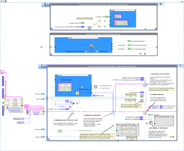
Please have a look at the VI itself, to see how it works! Just note that the cluster passed through the VI holds most of the needed information like current time, time of the alarms (...)
This way only one wire has to be passed, and the code looks cleaner. Since the code is running on an FPGA, we tried to parallelize as much as possible, to make the personality fit on the FPGA.
REAL TIME CONTROLLER
The surveillance module is running on the RT controller. The main VI is called RT_Main.vi. It is implemented as a state machine, which you can observe in the following diagram:
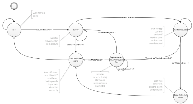
The attached code also contains a bitfile, so you don't have to recompile!
Product Marketing Manager for CompactRIO & TSN
Making the intangible, tangible
