- Document History
- Subscribe to RSS Feed
- Mark as New
- Mark as Read
- Bookmark
- Subscribe
- Printer Friendly Page
- Report to a Moderator
- Subscribe to RSS Feed
- Mark as New
- Mark as Read
- Bookmark
- Subscribe
- Printer Friendly Page
- Report to a Moderator
Team Strikeout: PitchPALS, Rice University 2011
Contact Information
University: Rice University
Team Member(s): TEAM STRIKEOUT: Ashley Herron, Henry Zhang, Jenny Sullivan, Pete Hoagland, and Sharon Du
Faculty Advisors: Gary Woods
Email Address: teamstrikeout@gmail.com, anh3@rice.edu, qz1@rice.edu, jls3@rice.edu, prh1@rice.edu, xd1@rice.edu
Project Information
Title: PitchPALS: Pitch Pressure Analysis and Logging System
Description:
PitchPALS (Pitch Pressure Analysis andLogging System) is inspired by the lack of effective devices in baseball gripdetection and analysis in all level baseball pitching trainings. The system utilizes force sensing technology on the surface of the baseball and embedded processing circuits inside of the ball to record and present detailed gripposition and strength of a pitch, and it also synchronizes with a full-body motionrecording to help pitchers and trainers to best visualize and improve pitching techniques.
Products:
NI Elvis II+ Board and related Elvis Board LabVIEW VIs
NI Multisim
NI Ultiboard
NI LabVIEW
NI DIAdem
NI High-Performance Camera Link Frame Grabber Card PCI3-1433
NI LabVIEW example code for frame grabbing
The Challenge:
PitchPALS, Pitch Pressure Analysis and Logging System, is a baseball- training tool for grip analysis. It provides comprehensive data on a pitcher’s grip over the course of the entire throw. It collects information about the contact points between the hand and the ball as well as how much force is applied at each point. This data is synchronized with high- speed video data in a convenient user interface.
This data is collected through a replica baseball that has been tiled with force sensors on the outside. This is called the PitchPALS Baseball. The PitchPALS Baseball is to be thrown by the pitcher like an ordinary baseball. It actively records the force data from each sensor to provide the desired grip data. This data is displayed in a 3-D color map, giving the user an easy way to see the data.
There is also an accompanying motion capture video that records the motion of the entire body. The video is synchronized with the sensor data. Not only does this provide another source of data for grip analysis, but it also acts as a reference by correlating the sensor data to a specific point during the pitch.
The Solution:
A. PitchPALS Baseball
1. Mechanical Ball Design
a. OuterShellDimensions:Theshellofthebaseballismodeledin SolidWorks and made of ABS plastic. The thickness is set to 5.08mm to accommodate the size of the PCBs. The outer diameter of the shell is set to 72mm in order for the ball to be the size of a real baseball.
b. Ledges:TheinsideoftheshellhasledgestosupportthePCBs inside. The length and location of each ledge was designed to accommodate for the larger electrical components on the PCBs. Each ledge is also designed to have 3mm of clearance over the boards. The vertical edge of each ledge is 1.3mm upper edge forms a 10 degree angle with the horizontal.
c. Slits: The shell has rectangular slits to allow the sensor leads to feed into the ball. The dimensions of each slit, which can be found in Appendix I of the binder, vary depending on how many sensor leads are being fed into it. The larger slits allow enough room for six sets of leads and smaller allow for four. The slits on the male half of the shell are centered, but the ones on the female are offset because of the ledges on the outside is covered by plastic wrap to protect the sensors.
d. InsidetheShell:Thewirescomingfromthesensorsaresecured to the inside of the shell with putty. Care was taken to make sure the leads were flat against the shell to prevent them from being twisted. This ensured a secure connection.
e. Rings:EachPCBissurroundedbyaplasticring,whichallowsthe board to rest on the ledges without hitting any components. The rings also provide stiffness to prevent the boards from bending when the ball hits the glove(figure 4).
Figure 5: Each PCB is surrounded by the plastic ring for added stiffness and to protect the components from touching the ledges.
2. Electrical System Overview
a. Gripsensing:PitchPALShas28piezoresistivesensorsalongthe seams of the baseball. When force is applied to the sensors, the resistance will change linearly. The piezoresistive sensors are connected in voltage dividing circuits, which will translate the force data to analog voltage proportionally.
b. Analogtodigitalconversion:Duringthepitch,theforcedatafrom 28 sensors are controlled by four 8-to-1 multiplexors. All the data from 28 data sources are cycled through and sent to two 2-channel ADCs for analog to digital conversion.
c. Data processing: The converted digital data is read by MSP430 and stored into internal memory. Once then the PitchPALS baseball reads 0 for all of the sensors, signifying the release of the ball, the program stops recording and waits for the transmission trigger.
d. Transmission:PitchPALSsystemusesUARTtransmissionfrom the MSP430 to the desktop computer station. Pressing the button on the surface of the ball triggers the transmission. Currently, the system uses a USB interface to receive on a PC.
i. Video Capture: During the pitch, we have a camera recording the full body motion of the pitcher for reference. We use Camera link as the interface and a frame grabber card. The video system saves the footage in .AVI format using a custom VI.
e. SynchronizationinGUI:Thevideofileandcorrespondingsensor data are loaded into DIAdem for easy data viewing.
3. Hardware Details
a. Sensors:WechosetouseFlexiForce®piezoresistivesensors because of their linearity, passivity, and ease of use. These piezoresistive sensors act as a potentiometer for force, which makes creating a circuit for determining the force fairly straightforward and simple. We used the sensors with 2” leads because of the small area of the baseball. We have 28 of these piezoresistive sensors lining the seams of the outside of the PitchPALS baseball.
b. ResistorforVoltageDivider:Wechosethevalueof10MΩforthe resistor in the voltage dividing circuit with the piezoresistive sensor because this gave us the greatest range of voltages from reading zero when there is no force to reading about 2.6V [with reference 3.3V] with a great amount of force. We have one resistor for each of the sensors, so we have 28 10MΩ resistors.
c. Multiplexers: We chose Texas Instruments’ 8-Channel Analog Multiplexer/Demultiplexer for our multiplexor to choose which sensor to read from at any given time. We chose this particular multiplexer because of its small size, fast settling time and number of inputs. We have 4 of these multiplexers, 2 on each of the top and bottom boards, 1 for every 7 sensors.
d. Analog-to-DigitalConverter:WechoseTexasInstruments’12-bit, 4-Channel Parallel Output Sampling ADC for our analog-to-digital converter. We chose this part because of its low current draw and fast settling time. Originally we were going to have more sensor inputs so we needed the multiple channels this ADC offers, but in our final design we only used 2 of the channels on 2 ADCs.
e. Processor:WechoseTexasIntruments’MixedSignal Microcontroller MSP430F5438 for our microcontroller. We chose this device family initially because we are familiar with the programming techniques for programming a MSP430, as well as its low power. We chose this specific device because it had enough I/O pins to satisfy all of our requirements for the digital data coming in from the ADCs. We have one microprocessor located on the bottom of the main board.
f. Bluetooth Chip: We chose to use Rayson’s BTM-182 Bluetooth module for our Bluetooth connection. We originally chose this module because it was the smallest fully functional UART connected Bluetooth module with reasonable current draw we could find. Ultimately our power regulator still could not handle its amount of current draw, so the Bluetooth chip was not included on our final design.
g. PowerSource:WechoseaTadiranlithium1⁄2AAbatteryforour power source. We chose this battery because of its reasonable size with respect to its current load capabilities. The battery holder is soldered onto the top board, but the battery is strategically located in the center of the PitchPALS baseball.
h. VoltageRegulator:WechoseTexasInstruments’Dual200mA Output, Low Noise, High PSRR, Low Dropout, Linear Regulator for our voltage regulator. We chose this regulator because it was capable of taking our battery of 3.6V and having a dual output of 3.3V, also because of it’s current draw abilities. Ultimately, we found that there was an issue with the specified current draw the regulator is supposed to handle and the amount it is capable of
handling. We have one voltage regulator place on the bottom of the top board next to the battery.
i. UART to USB Adaptor: Once we realized the Bluetooth was not
going to be able to work within our time frame, we decided to find a UART to USB connector so we could communicate with our board without having to change the MSP430 code at all. We chose Cytron’s UC00A USB to UART converter, which is capable of sending and receiving UART signals at 3.3 and 5 volts. There is a header on our board that connects to the adapter when it is time to upload the data.
These components are put together onto three circular PCBs that fit into the ledges on the inside of the baseball shell. The top and bottom PCBs are the same with the sensor headers, resistors for the voltage dividers, and multiplexors. The top and bottom PCBs both have the connections for the battery and power regulator, but only the top board has these components attached. The middle or main board is the processing board, which includes the MSP430, ADCs, debugging LEDs and buttons, as well as the connection for data transmission.
4. Software Details
a. Main Software Used
i. Pre-Prototype Development National Instruments Elvis II+ and related LabVIEW VIs
ii. Board Design National Instruments Multisim and Ultiboard
iii. On-Chip Software Development Texas Instruments Code Composer Studio v.4
iv. Video Capture Development National Instruments LabVIEW
v. GUI Development National Instruments DIAdem
b. MSP430 Code Design
The MSP430 controls the entire system inside of the PitchPALS baseball. It controls which sensor is being read from by selecting a channel on the mux and the ADC. It also has an output for the ADC’s clock. The MSP430 saves the incoming data and stores it until it is uploaded onto the desktop.
1. Initialization
a. UARTinitialization
i. The UART output for the data transmitter, originally Bluetooth but then switched to a wired UART connection, is set to work as a UART and not GPIO.
ii. The clock for the UART is set to the SMCLK and then is divided for a BAUD rate of 115,200.
b. Clockinitialization
i. The ACLK source is set to the DCOCLK and set to 8MHz.
ii. The SMCLK source is also set to the DCOCLK and set to 8MHz.
iii. The MCLK source is also set to the DCOCLK and set to 8MHz.
iv. The output for the ADC clock is set to the ACLK and is divided to be 2MHz on the output.
c. Timer initialization
i. The timer is set to run off of the 8MHz SMCLK, in up mode, and with the clock divided by 8.
ii. The timer is set to count up to 0x7FFF.
iii. The timer interrupts are then enabled.
d. GPIOinitialization
i. All of the inputs and output are set to be the correct input or output.
2. Mainloop
a. Mux: The select pins for the MUX are set to be the current count of 1 through 7.
b. ADC: The output pins to both of the ADCs are changed individually to the correct values in order to read from the ADC as shown in the figure below. The program waits for the busy signal of each ADC separately to go high then reads from each of the ADCs’ digital pins.
c. Save data: The most significant 8 bits of data from both of the ADCs are save from their temporary variables into the permanent circular buffer.
d. Check:Oncetherehasbeenafullcyclethroughall28 sensors the value of each of these readings is checked to decide if the ball is still being gripped. If each of the readings is still above the threshold then the cycle continues, but if it is below the threshold it will wait for the button to be pressed to transmit the data.
3. Transmit data
a. The program waits for the press of a button to transmit the data.
b. The data is transferred as groups of all of the samples for each the sensors.
4. Wait
The program then waits for the button to be pressed again to signify the start of a pitch and the process starts over again.
c. Code and software for uploading data
The current upload process takes multiple steps, but each of them is not very complicated. In general, the data needs to be uploaded and decoded in order to be meaningful.
1. Upload
a. Hyperterminal is used to upload the UART data on to the computer
b. Before pressing the button on the PitchPALS baseball set Hyperterminal to record the incoming text into a text file.
2. Decode using the parser
The parser takes the saved text file that is composed of ASCII data and formats it as integers that can be read by the user interface and saves it in a new text file.
B. Video Capture
1. Hardware Details
i. Camera: Digital CMOS Area Scan Camera Link Output, Basler A504k, borrowed from Brent Runnels from National Instruments
ii. Frame Grabber Card: High-Performance Camera Link, National Instruments PCIe-1433, donated by National Instruments
2. Video Capture
The video is captured and recorded using a custom made LabVIEW VI. We created a VI that will store a specified number of frames until the save button is pushed then it will save the saved frames into a .avi file with the name chosen plus the current time stamp.
1. The VI starts by initializing the framegrabber card and the buffer for saving the frames.
2. It runs in a continuous loop saving the frames on a circular buffer. This general structure was found in an example provided by LabVIEW.
3. When the save button is pressed the program tells the frame grabber card to stop grabbing new frames and begins saving them.
4. To save the program opens a new .avi file with the name specified plus the current time stamp and begins saving all of the frames one by one from the buffer.
5. Once all of the frames have been saved, the .avi file is closed and the frame grabber card is reinitialized and the process starts over.
6. There is a manual stop button to safely close the program.When the stop button is pressed the program closes all connections to the frame grabber card and to any .avi file it might have open.
C. User Interface
1. Software
The PitchPALS user interface is created using NI DIAdem, a data viewing and synchronization software. The interface has a plurality of visual elements, including the motion capture video, a 3-D color model of the ball, a numerical data table, and a notes section for the user to input notes about the pitch.
a. Video:The video window is generally placed in the upper left hand corner of the interface screen to maximized visual effectiveness. A video can be loaded directly into the video window by choosing load video from the right-click menu. The video format should be .avi. The video is typically not compressed and will play directly. Otherwise, refer to the DIAdem Video Requirements section in the Appendix.
b. 3-D Model: The 3-D model is in the right upper hand corner. The model itself is a Solidworks rendering of a baseball. This .stl file is loaded directly through the right-click menu. After channels are applied, it will be a color map whose color changes with change in sensor data.
c. Channels:Datachannelsareloadedinthestartscreenandplaced on the right hand side of the screen. Each data channel is dragged and placed on the corresponding location on the 3-D model.
d. DatatableandTimeAxis:Belowthevideoand3-Dmodelarethe time axis and data table. The data table is a matrix contained each sensors samples over the data collection period. The time axis graph shows each sensor’s value over time
e. Notes Area: There is an area in the bottom left corner that is a text entry window. The user than input information regarding the pitch such as pitcher name, date, type of pitch, result, weather, etc.
2. Synchronization
The video clip and 3-D model are synchronized through cursor synchronization. The Speeds of the video and 3-D model are individually adjusted to play at the same speed. The user can then drag the mouse along the time axis to focus on specific time points.
D. Uses and Benefits of LabVIEW and other NI tools
1. NI Elvis II+ Board and related Elvis Board LabVIEW VIs
The Elvis board was very useful when testing the Flexiforce pressure sensors linearity and testing the circuits before designing the PCBs. The oscilliscope, DMM and other similar functions were used extensively when designing and debugging the boards inside the PitchPALS baseball.
2. NI Multisim and Ultiboard
Multisim and Ultiboard both have intuitive user interfaces that made designing the needed components as well as the schematic and PCB design for our boards uncomplicated. They allowed us to focus on the design of the board instead of taking unnessicary amounts of time learning how to design the schematic and board.
3. NI LabVIEW
LabVIEW made interfacing with the NI hardware extremely straightforward. Also, LabVIEWs example code helped in learning the new coding language.
4. NI DIAdem
DIAdem made making an intermediate user interface quick and easy. The syncronization features of DIAdem was the most useful tool in being able to view the video data with the pressure data.
5. NI High-Performance Camera Link Frame Grabber Card PCI3-1433
The NI frame grabber card was very useful for interfacing with the camera and using LabVIEW made recording the grabbed frames from the camera clear.
E. Images and Figures
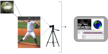
Figure 1: Full System Overview
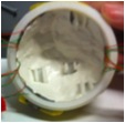
Figure 2: Inner surface of shell: ledges hold PCB's in place, and sensor wires are coverd by putty
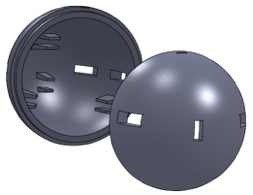
Figure 3: SolidWorks model of shell: Slits allow sensor wires to feed inside the ball to connect to the boards.
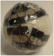
Figure 4: Fully constructed ball covered in plastic wrapping
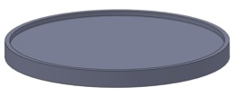
Figure 5: Each PCB is surrounded by the plastic ring for added stiffness and to protect the components from touching the ledges
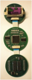
Figure 6: Three circular PCBs connected in series laid out flat
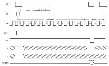
Figure 7: Timing model for a read from the ADC
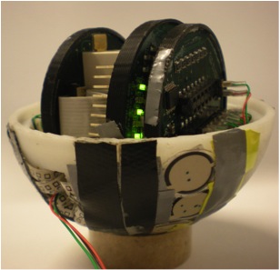
Figure 8: Side view of the inside of a fully connect PitchPALS baseball.
F. Video Overview of Project
http://www.youtube.com/watch?v=cD_YOuhTPqY&feature=player_embedded
- Mark as Read
- Mark as New
- Bookmark
- Permalink
- Report to a Moderator
Hello there,
Thank you so much for your project submission into the NI LabVIEW Student Design Competition (Go Owls). It's great to see your enthusiasm for NI LabVIEW! Make sure you share your project URL with your peers and faculty so you can collect votes for your project and win. Collecting the most "likes" gives you the opportunity to win cash prizes for your project submission. If you or your friends have any questions about how to go about "voting" for your project, tell them to read this brief document (https://forums.ni.com/t5/Student-Projects/How-to-Vote-for-LabVIEW-Student-Design-Projects-doc/ta-p/3...). You have until July 15, 2011 to collect votes!
I'm curious to know, what's your favorite part about using LabVIEW and how did you hear about the competition? Great work!!
Good Luck, Liz in Austin, TX.
