- Document History
- Subscribe to RSS Feed
- Mark as New
- Mark as Read
- Bookmark
- Subscribe
- Printer Friendly Page
- Report to a Moderator
- Subscribe to RSS Feed
- Mark as New
- Mark as Read
- Bookmark
- Subscribe
- Printer Friendly Page
- Report to a Moderator


Contact Information
University: Sungkyunkwan University, Korea
Team Member(s): Ki-Yong Shin, Ahn-Ryul Choi, Su-Hyun Youn, Jin-Sung Song, Dong-Jun Lee, Su-Bin Joo
Faculty Advisors: Prof. Joung-Hwan Mun
Email Address: avery@skku.edu
Project Information
Title: Surgical Navigation for Total Knee Replacement(TKR)
Description:
In surgical operation, which needs cutting bones, and replacing artificial implants, operating navigation works as computer surgery aid-system that can helps doctor's decision making. Two cameras using infrared light were used in this project, thereby point matching algorism that can track markers attached to lower-body joint model were developed, and marker data acquired in pervious step were used in kinematic body modelling. The model repeated movement of lower-body joint in real time at 3 dimension, which is the core technology at total knee replacement, and angle of knee-joint was given by calculating X, Y, Z, three directional results. With this system, the effect of surgery can be proved by comparing movable range of knee-joint before and after surgery.
Products:
- National Instruments LabVIEW 2009(Student Edition)
- National Instruments Vision Acquisition software
The Challenge:
As the time change, people have desire to increase quality of life, and it leads increase of importance and interest about health. Adjust to tendency, existing medical systems start to integrate with high technology. Especially, lots of computer aid equipments are developed to help surgeon during surgery. Regardless of efficiency or experience of doctor, surgery can warrant high chance of success with this system. In this project, navigation system for total knee replacement(TKR) is developed with Labview.
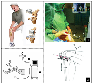
<Fig 1. Surgical navigation system>
The surgical navigation system for TKR is surgery that replacing part of damaged knee bone with artificial knee joint in the case of knee joint injury such as degenerative arthritis. In this system, chasing alignment angle of knee in real time is core technology. Technic below are needed to materialize this system.
- Acquiring 3 dimensional coordinate from 3 markers attached in femur and tibia each by two multiplex cameras.
- Anatomical landmark acquisition of femur and tibia.
- Anatomical axis restore about femur and tibia in virtual space with acquired coordinate
- Calculating knee joint angles(Flexion/Extension, Abduction/Adduction) from restored two axises
Core technologies above are restored through Labview. Also, 3D bone model display and knee joint angle are embodied in real time.
The Solution:
1. Point matching technic with two infrared light utilized camers
As a kernel part of this study, two cameras mounting infrared light are used to acquire image. Each camera connected to computer, and 2D images are acquired by NI IMAQdx supplied from NI. It helps the image acquiring process handy, and algorism can be embodied fast and easily with Labview. Also, using various debugging function makes finding errors in realtime, and shortening development time.
Finding corresponding point between acquired 2D images from two cameras is necessary to 3 dimensional restore of object and can be said as one of core technic. As a method, diverse camera geometries: epipolar constraint, fundamental matrix, homography, stereo rectification, and etc, are applied.
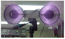
<Fig 2. Infrared light utilized cameras>
To get actual image, calibration step is needed beforehand. Through calibration, position of captured marker from two cameras can be calculated in 3D coordinate. There are several ways for calibrating more than two cameras, in this experiment method that using calibration frame which accurate marker points are already known was used.
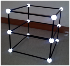
<Fig 3. Three dimensional calibration frame>
Direct linear transformation (DLT) algorism which used in calibration needs at least 6 markers. For 12 unknown values calculation 6 markers were needed because each marker only produce an equation for u, and v separately.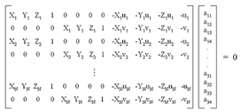
After calibration step above, image was acquired by each camera in realtime. Lower-body joint model used in this study has 3 markers on femur, and tibia each. With this, marker tracking and 3 dimension coordinate restoration were done as image acquired in 30 frames per second at real time.
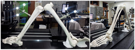
<Fig 4. Lower-body model and markers>
The equation to calculate 3 dimensional coordinate with two cameras is like below. In programming process, utilizing Labview comes with several advantages, allowing brief realization of complicated function, realtime confirmation, and ease debugging process.
2. Kinematic modeling of Lower-body using anatomical landmark
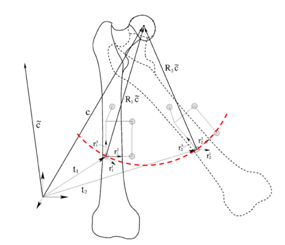
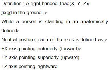
Overall kinematic modelling process of lower-body joint is shown on figure. First, in order to extract rotation center of hip joint, optimization strategy was applied in this study. Center of rotation calculated based on anatomical coordinate-system, and in this system pelvis was fixed in . 3 dimensional x, y, z coordinate of hip joint were used as design variables, and cost function expressed like as <equ.> with assumption that hip joint(ball and socket joint) makes spheric motion in 3 degree of freedom. For optimization strategy, least square method which used in general was applied.
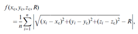
<Fig 5. Hip joint center calculation>
To build anatomical coordinate system, 6 anatomical landmarks were needed other than rotation center of hip joint. 6 anatomical landmarks consist with medial epicondyle, lateral epicondyle of femur, and medial condyle, lateral condyle, medial malleolus, lateral malleolus of tibia, and these landmarks were computed in a roundabout way with probe.
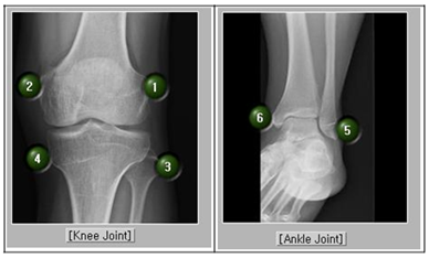
<Fig 6. Anatomical landmark>
Probe was designed to solve a problem with marker conceal phenomenon, and it is an implement that trace position of target spot indirectly with two markers settled at the end. Therefore, in a condition that length information of probe was already acquired, coordinate of target point was acquired in real time from two markers on probe.
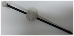
<Fig 7. Prove to acquire anatomical landmark reference>
<Fig 8. Anatomical landmark acquisition>
Extracted anatomical landmarks were saved after coordinate conversion based on the local coordinate system about the thigh and lower leg, and displacement of anatomical relative-angle was computed through realtime coordinate conversion and marker chase. Anatomical relative-angle was calculated with angle-coordinate system in general use.
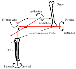
<Fig 9. Joint reference system>
3. Materialization of 3 dimensional joint model of Femur and Tibia designed with 3D graphic tool(CAD)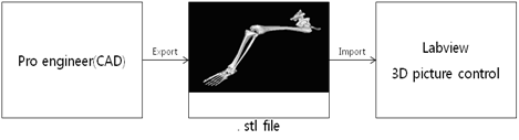
<Fig 10. 3D model restore steps>
Designed file(.stl) with 3D graphic tool(Pro Engineer) was imported to Labview. Each segment of lower body was imported separately, and connected to compose skeletal model. Composed lower body joint model repeats the movement of real skeletal model in 3 dimension.
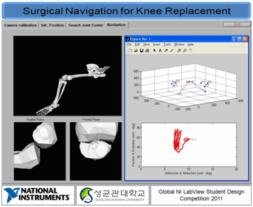
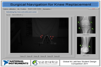
<Fig 11. Performance of navigation system>
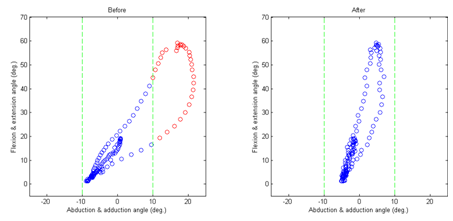
4. Aligment angle difference of knee before and after surgery
Utilizing reference of lower-body joint changes in real-time can calculate abduction & adduction angle and flexion & extension angle. Angle values calculated before surgery and after surgery are used to quantity compression of surgery result.
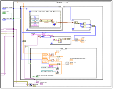
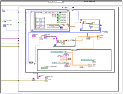
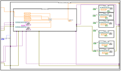
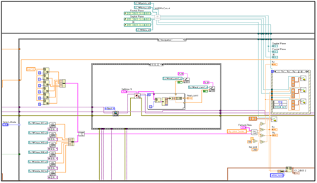
5. Labview source code
1) Camera calibration
2) Set initial position
3) Search joint center
4) Navigation
- Mark as Read
- Mark as New
- Bookmark
- Permalink
- Report to a Moderator
Amazing. I thought Labview is simply graphical language. But this project is art.

- Mark as Read
- Mark as New
- Bookmark
- Permalink
- Report to a Moderator
Good job. Have a nice day!
- Mark as Read
- Mark as New
- Bookmark
- Permalink
- Report to a Moderator
Thank you for your attention and great efforts on this projects.
I`ll cross my fingers for your good results
Hope to keep better solution with LabVIEW.
- Mark as Read
- Mark as New
- Bookmark
- Permalink
- Report to a Moderator
It's great.
I hardly believe that it's done by manily students.
This is pretty practical application, I believe.
Once again, well done, keep on doing what you have been doing so far.
This could be even greater later.
Good luck with a competition.
