- Document History
- Subscribe to RSS Feed
- Mark as New
- Mark as Read
- Bookmark
- Subscribe
- Printer Friendly Page
- Report to a Moderator
- Subscribe to RSS Feed
- Mark as New
- Mark as Read
- Bookmark
- Subscribe
- Printer Friendly Page
- Report to a Moderator
Real-time Vision Sorting of Paintball Media, USA
To vote for this project, click the "LIKE" button at the bottom right of this post. Thanks!
Contact InformationUniversity: Rose-Hulman Institute of Technology Team Members: Michael Bell, Kevin Risden, Thomas Hazelrigg, Stephan Lemmer Faculty Advisors: Dr. Patrick Cunningham Email Address: bellma@rose-hulman.edu Country: United States of America |  |
Project Information
Title: NI Ball Drop Demonstration - Real-time Vision Sorting of Paintball Media
Description:
This project is a demonstration to show the power of NI's Smart Camera system and computing power of the cRIO. The project accomplishes this by dropping a waterfall of different colored paintballs which are identified in real-time by the NI Smart Camera. The NI Smart Camera then controls an air valve stage which blows selected colors of paintballs out of the "waterfall" within milliseconds to different color sorting bins.
Products:
Smart Camera (1.6Ghz Atom Processor, VGA, Color) - NI 1772C
cRIO - 8-slot chassis, Real-Time PowerPC Controller 800Mhz (cRIO-9204, NI 9144)
Digital I/O Modules - 6x 32-channel NI 9403
NI LabVIEW
NI Vision
The Challenge:
Show the computing capabilities of the cRIO and Smart Camera in a visually and physically impressive demonstration geared towards NIWeek 2012. We accomplished this by creating a waterfall of reusable paintballs (simply rubber balls 0.7" in diameter) that is 60 channels wide and 6 feet tall. The balls can fall at rates up to 30 per second, almost 1200 falling at once! The NI Smart Camera is able to identify the balls as each row falls, which is explained graphically below:
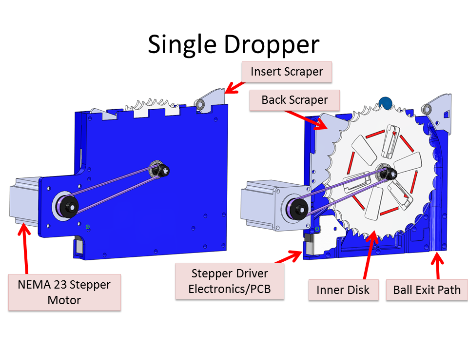
The core of the system was the droppers, which we created a total of 60. This is what the droppers looked like:
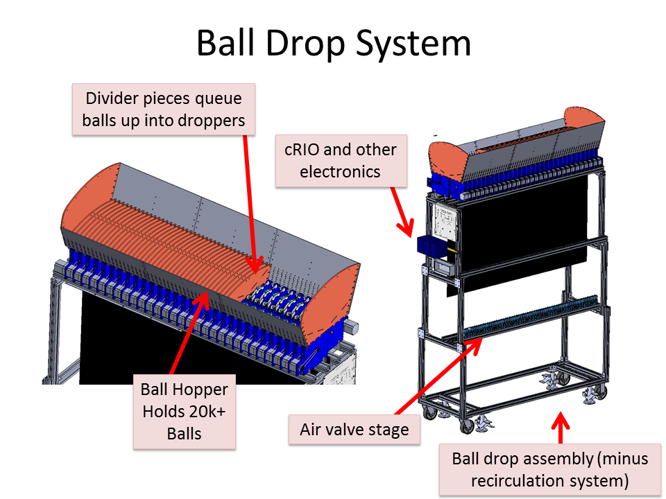
60x of the droppers were integrated into the larger system which looked like the following:
The Solution:
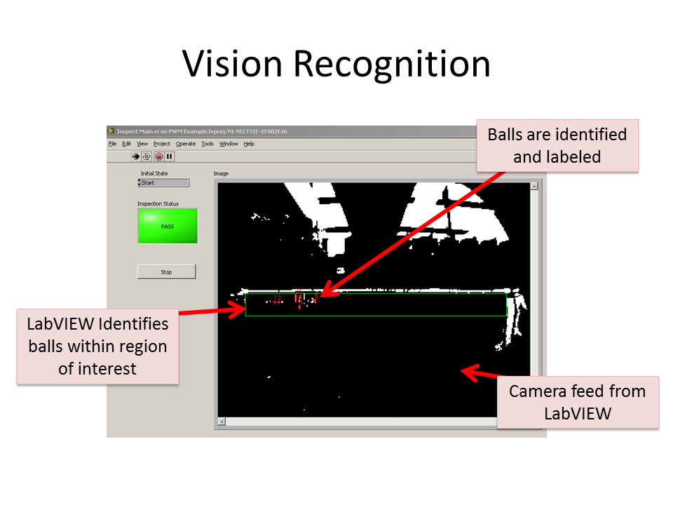
Turning CAD into actual objects was a huge deal in this project. Once the mechanical portion was complete we moved onto the LabVIEW portion. A vision recognition program was created that was able to identify falling balls in real-time. The graphic below shows a screen capture from our program. As you can see there are a number of identified white balls that are in the area of interest (the green box). The program using NI Vision creates a red box around the balls of interest and labels them with what channel they are in.
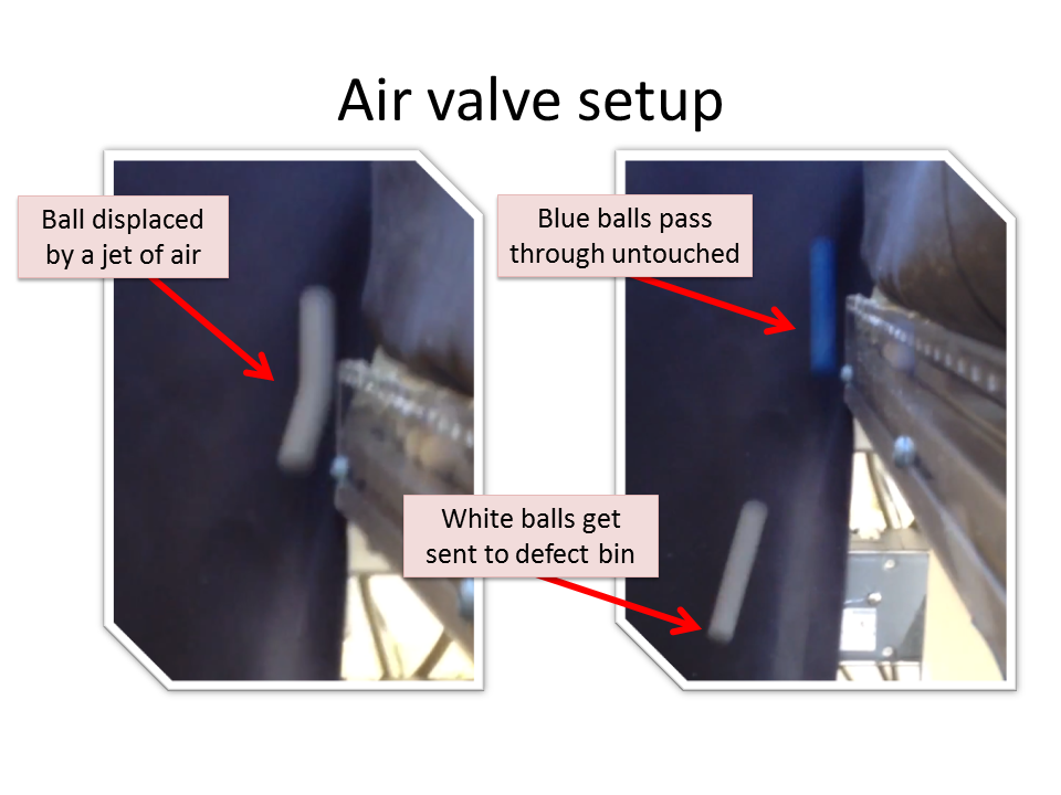
Next, the NI Vision program controls each channel's air valve and activates it for around 10 milliseconds right as the ball passes by the nozzle. The graphic below shows the deflection of the white ball, but the blue ball is able to pass through untouched since we are not sorting the blue ones.
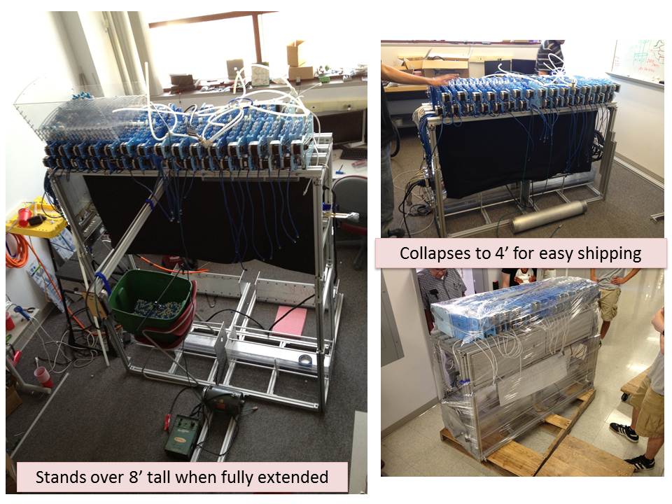
Finally, since the system is a demonstration it needs to be shipped. The frame was created in a way that lets it collapse to 4' during shipment, and extends all the way up to 8' tall for demonstration. A few pictures can be seen of this below.
Video:
We produced a video progress update for NI back in the beginning of May. The project was not completely finished at that point in time, but all aspects of the project can be seen:
More videos can be found here: https://picasaweb.google.com/103090073398423940872/NIBallDropPhotoAlbum
Additional Pictures:
We have over 800 pictures from our project, all can be found here: https://picasaweb.google.com/103090073398423940872/NIBallDropPhotoAlbum, but some additional pictures are posted here with captions:
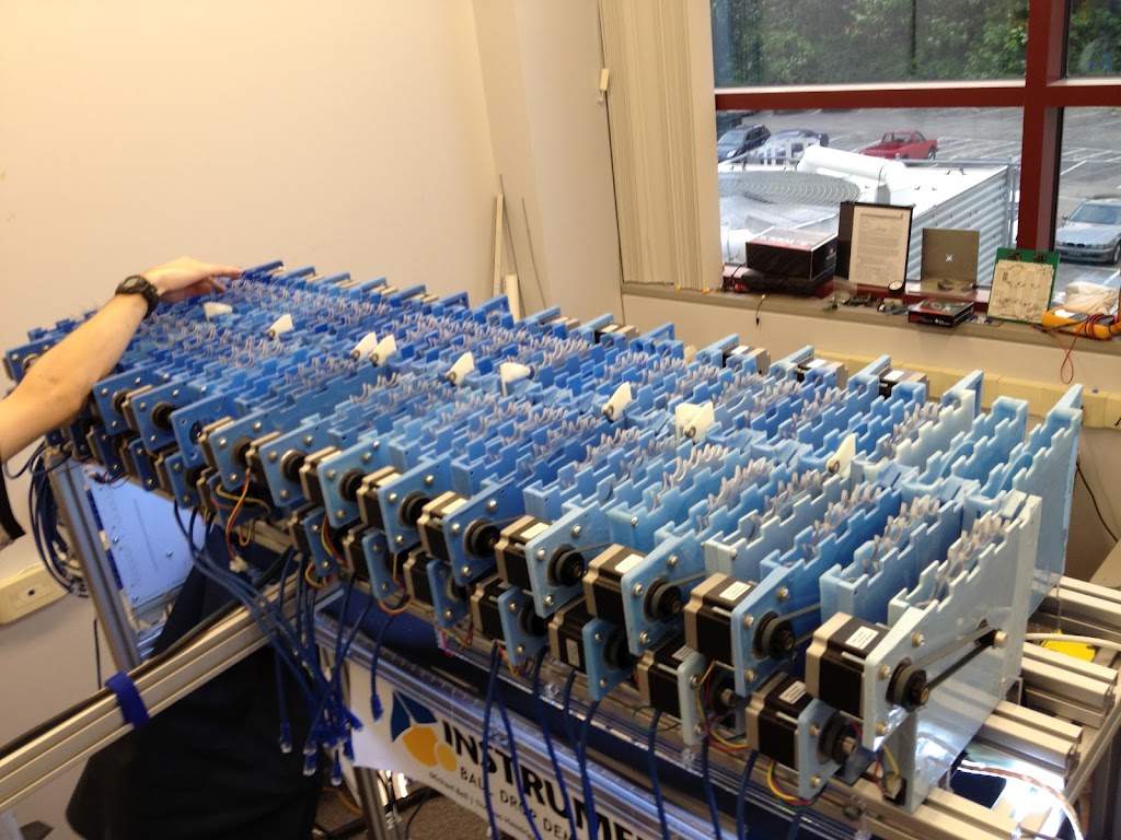
Almost all 60 droppers can be seen above. We purposely created a white to blue gradient in the colors of the droppers so it would look awesome!
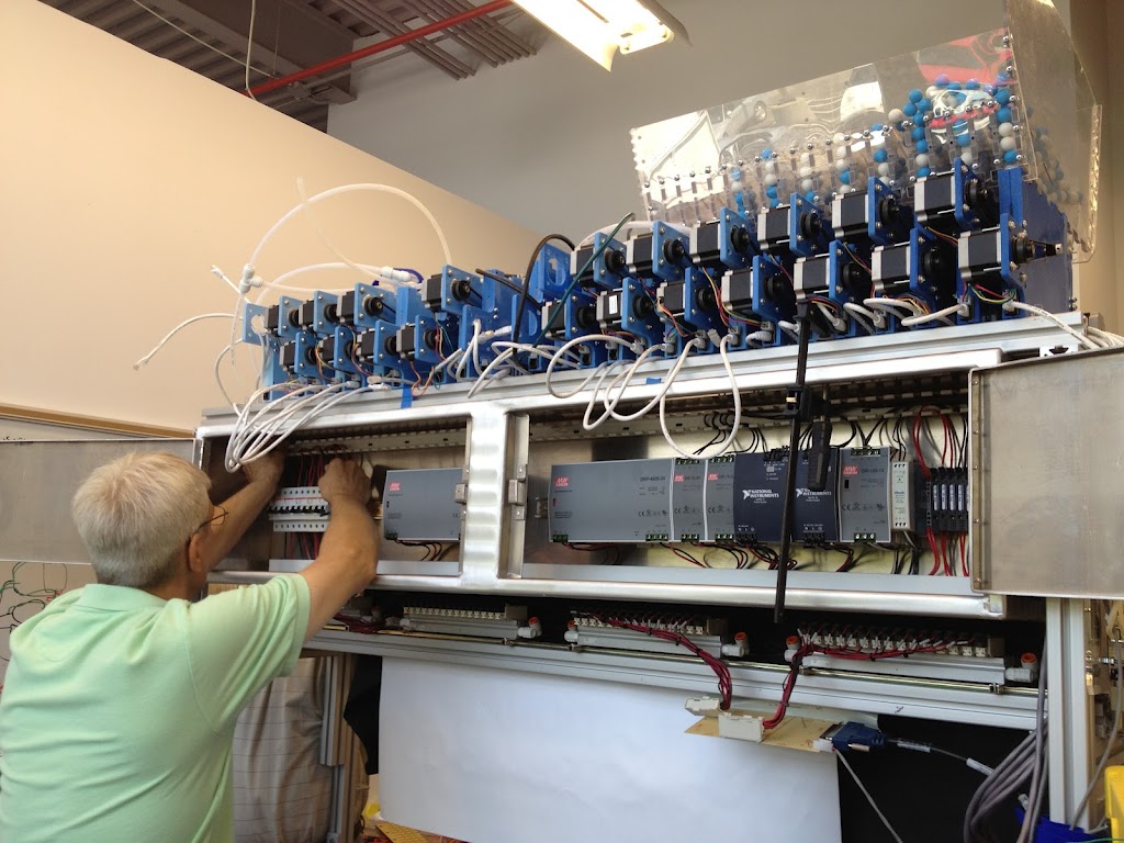
We need about 150Amps at 24v to power all the stepper motors in the demonstration. This electrical box is being worked on by a certified electrical technician as seen above.
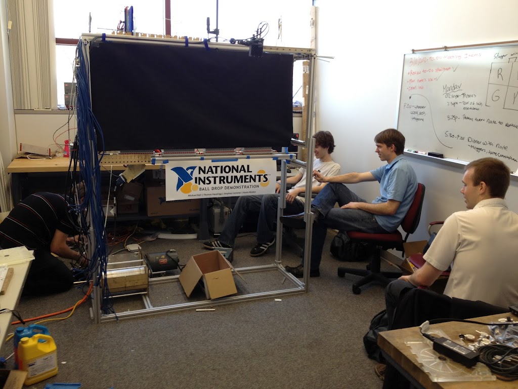
Our NI client Nate Holmes visits us back in April, 2012 (he's wearing the blue shirt of course).
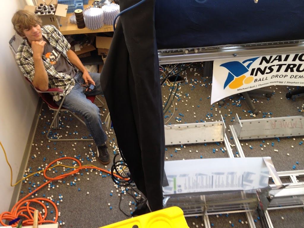
Testing the system creates a blue and white mess. Our team member Stephan Lemmer ponders how long it will take to clean up!
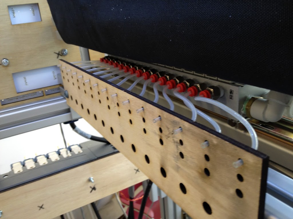
A plywood prototype air valve holder is seen with 15 valves. The flexible tube gets glued to the wood to stay in place.
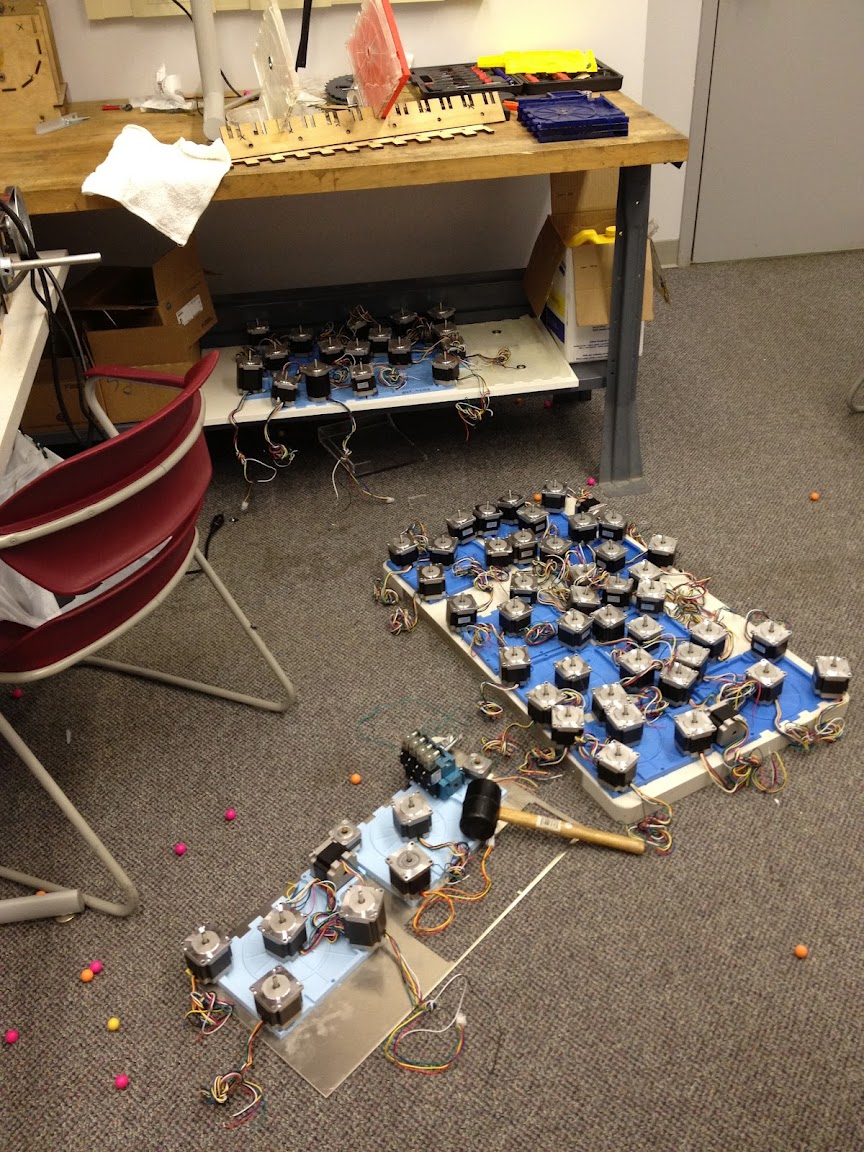
Tons of stepper motors are seen weighing down the fresh blue molds. The dropper molds tend to warp if not held down while they harden.
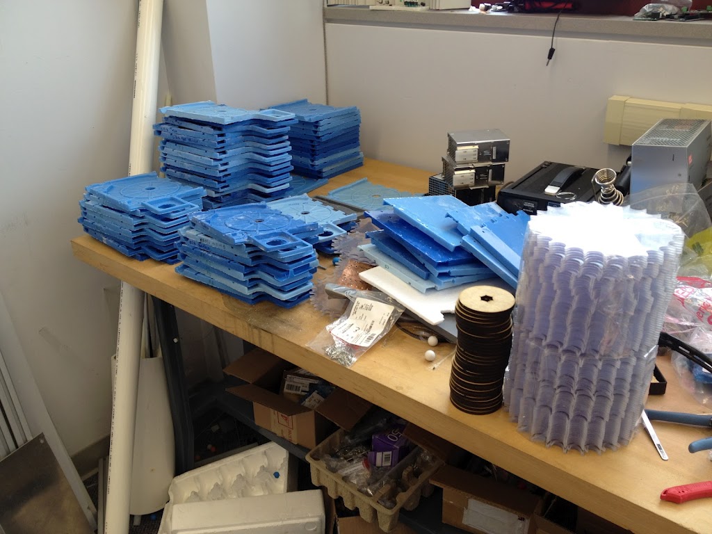
A large stack of blue molds completed, and a stack of disks that go into the dropper system to be assembled.
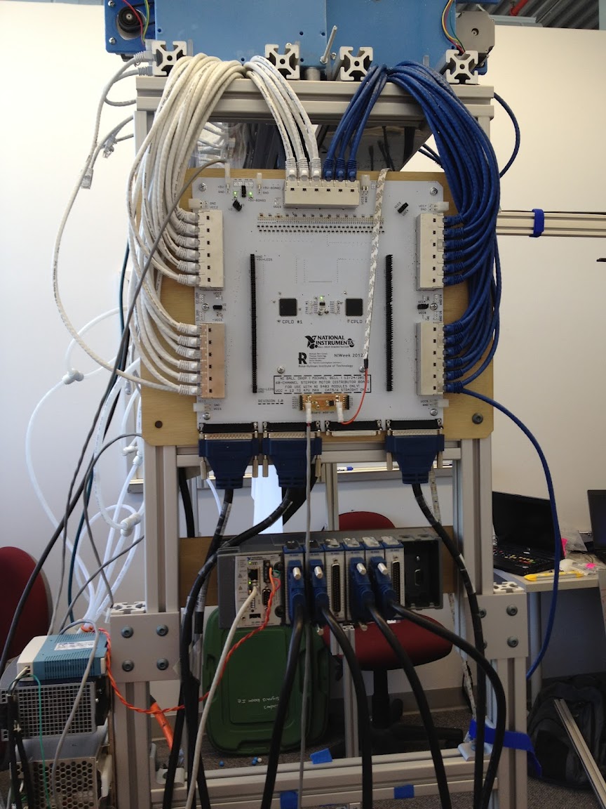
The cRIO and custom distributor board can be seen above. The distributor board takes in 4x DB-37 cables and distributes the digital signals and power over 60x individual cat-6 channels to each dropper. The droppers then control their stepper motor, which governs the rate at which the balls fall.
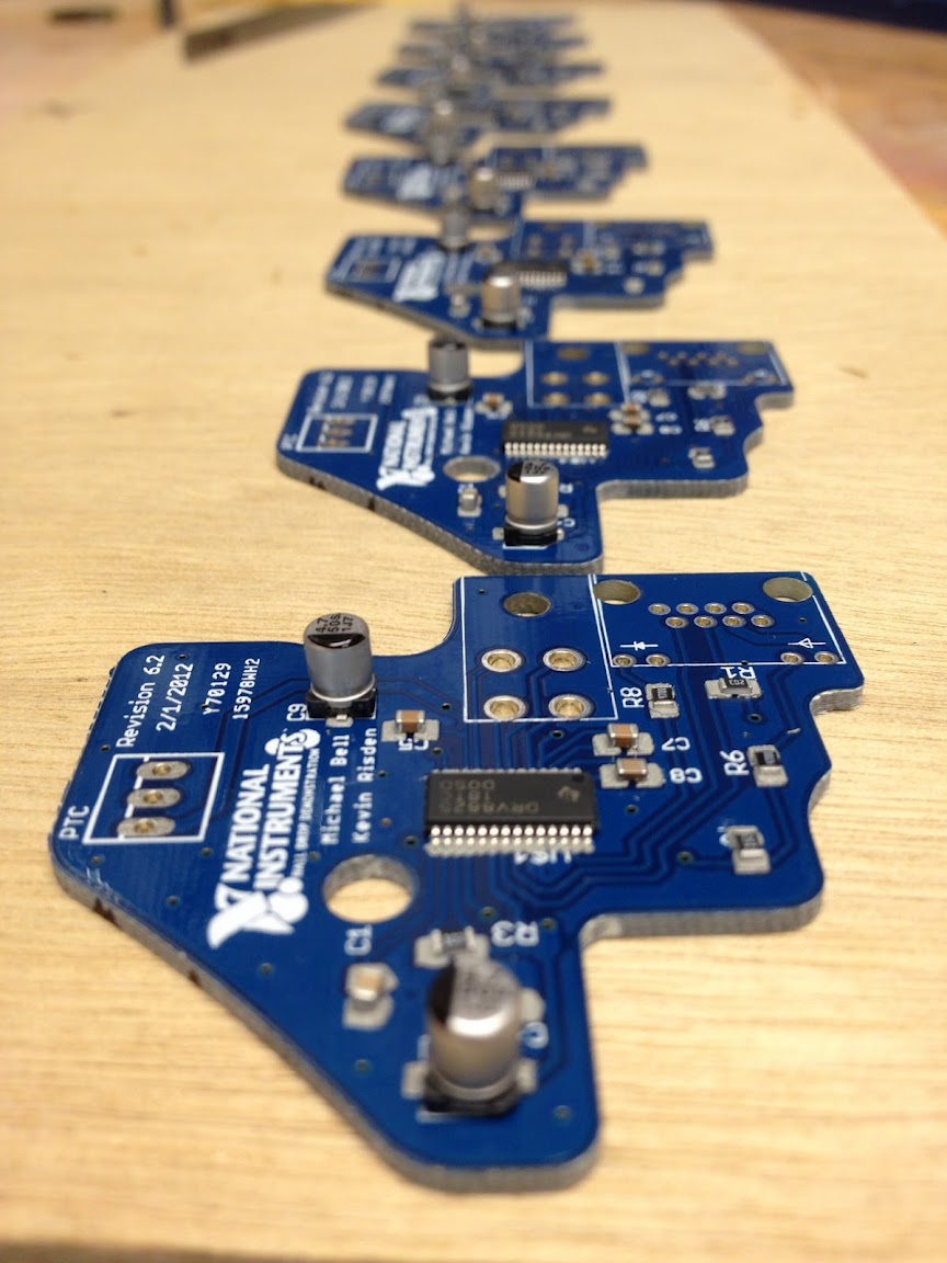
Each dropper needs a stepper driver board. Above you can see a few boards before they go through the oven to get reflow soldered. TI graciously donated all the stepper driver chips to our project.
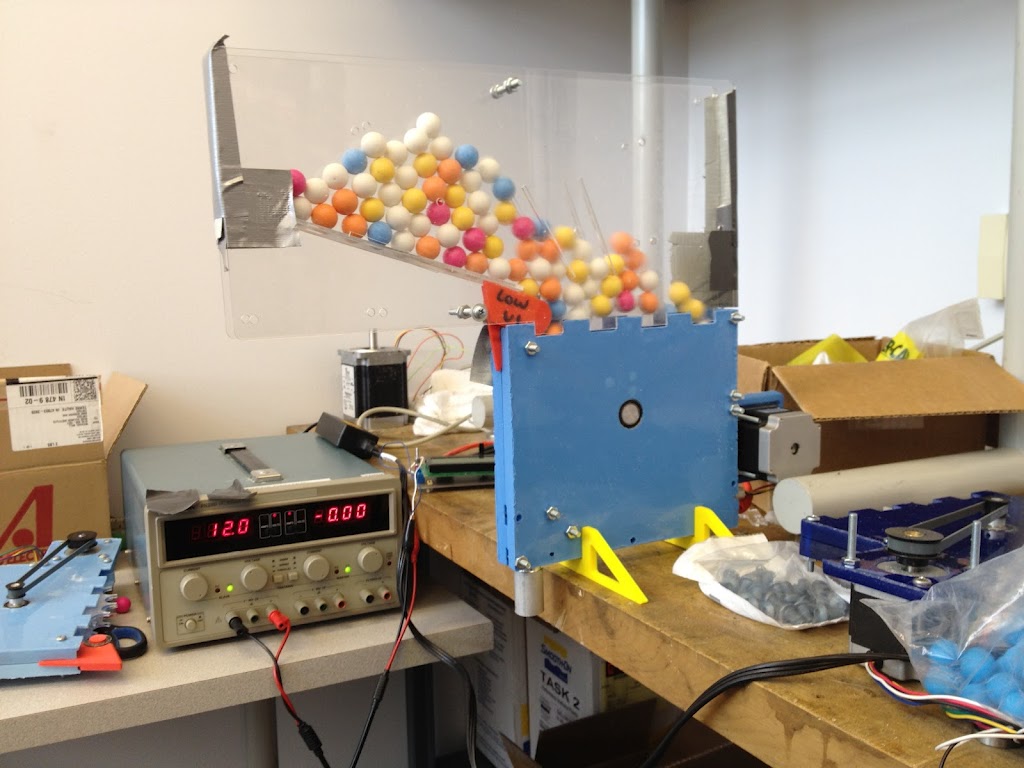
One of the first molds that we created can be seen above. We started with multicolored balls until a factory in China created special white and blue balls just for us (which are mixed in with the colored balls above).
Thank you for viewing our project!
To vote for this project, click the "LIKE" button at the bottom right of this post. Thanks!
- Mark as Read
- Mark as New
- Bookmark
- Permalink
- Report to a Moderator
Great job guys!
Keep up the good work!
We are so proud of you.
http://robotics.rose-hulman.edu
