- Document History
- Subscribe to RSS Feed
- Mark as New
- Mark as Read
- Bookmark
- Subscribe
- Printer Friendly Page
- Report to a Moderator
- Subscribe to RSS Feed
- Mark as New
- Mark as Read
- Bookmark
- Subscribe
- Printer Friendly Page
- Report to a Moderator
Contact Information
University: University of California - Los Angeles
Team Member(s): Derek Schaeffer
Faculty Advisors: Christoph Niemann
Email Address: dschaeffer@physics.ucla.edu
Country: United States
Project Information
Title: A Comprehensive Multi-Laser Control and Monitoring System
Description:
The goal of this project was to create a comprehensive laser control and safety interlock system for the multiple-laser Phoenix high-energy density physics laboratory.
Products:
Labview Products: Real-Time Module, FPGA Module, NI Vision Development Module, NI Motion Assistant, NI VISA
NI Hardware Products: NI CompactRIO-9072, -9073, and -9074 and Modules
Additional Hardware: Timing Boxes (BNC 565, DG 535), Scopes (TDS 2014, DPO 7254), Digitizers (CAEN DT5720), Detectors (AXIS GigE, AVT Manta, AVT Prosilica, DMK Firewire, DMK USB), Motion Controllers (Trinamic TMCM610, Thorlabs TDC001), and Gauges (Terranova 906A, TTK RC Chiller)
The Challenge:
Develop a laser control application - including safety interlocks, pulsed power, and diagnostics - for the three-beam Phoenix high-energy density physics laboratory.
The Solution:
Combine the reliability and versatility of NI CompactRIO and LabVIEW FPGA Module with a custom, modular LabVIEW application. This allows us to safely and remotely control and diagnose multiple high-power laser systems from any location in the laboratory.
Introduction
Collisionless shocks are ubiquitous in space plasmas, including solar wind hitting the Earth’s magnetosphere or the interstellar medium, supernova remnants, and high-altitude nuclear explosions. Unlike typical shocks, which are mediated by collisions between particles (such as air in a sonic boom), collisionless shocks are mediated solely by electromagnetic fields. While satellites can study in detail shock phenomena near Earth, there a few ways to directly observe shocks in more remote systems. With appropriate scaling of astrophysical parameters and lasers, however, we can study collisionless shocks in the Phoenix high-energy density physics laboratory at UCLA, a schematic of which is shown in Figure 1. The Phoenix lab consists of three high-energy lasers - Phoenix, Raptor (see Figure 2), and Peening - with corresponding pulsed power systems and assorted laser diagnostics. During a typical experiment, the Raptor laser is focused to a millimeter-sized spot on our target, which sits in a pre-formed, tenuous plasma and magnetic field. The intense laser pulse rips material off the target’s surface and ejects it at several hundred km/s. The resulting plasma explosion carves out a bubble in the magnetic field, which then collides with the ambient plasma, accelerating it to super(magneto)sonic speeds (see Figure 3). As the fast ambient plasma plows into stationary plasma, a collisionless shock is formed. The other lasers are used to probe the initial explosion and the formation of the shock.
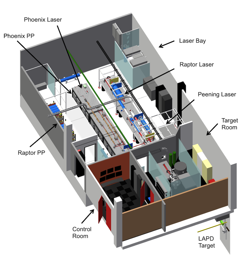
Figure 1: The Phoenix lab is comprised of the laser bay - housing the 50 J Phoenix, 1000 J Raptor, and 20 J high-repetition Peening lasers and associated pulsed power systems - a target room, and a control room. The lasers can also be sent through the floor to the Large Plasma Device (LAPD) for experiments.
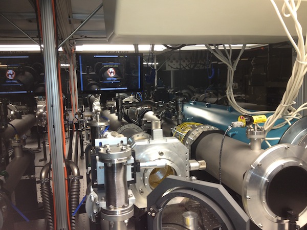
Figure 2: The Raptor laser is capable of outputting 1000 J in 50 nanoseconds once every 30 minutes. In addition to power systems, interlocks, and laser timing, cameras, motors, and gauges must also be controlled and monitored.
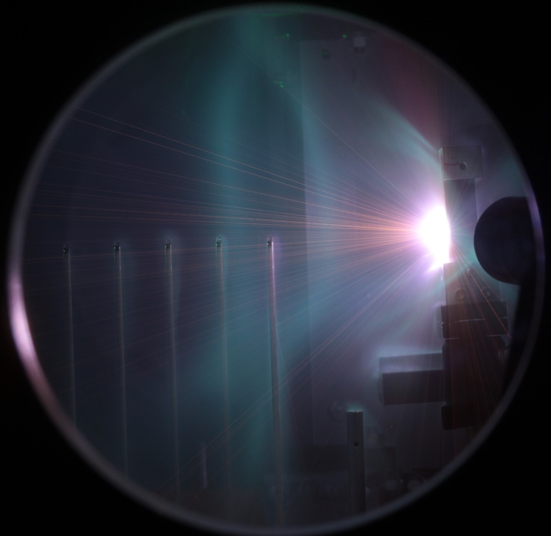
Figure 3: Image of a typical laser shot, taken with an SLR camera at long exposure. A graphite target is placed towards the right of the image. The laser hits the target, creating a plasma explosion that radiates intensely near the target's surface. Ballistic macroscopic chunks of carbon (orange streaks) can be seen radiating from the target. A tenuous green halo marks the boundary of the magnetic bubble, measured by magnetic flux probes positioned radially from the target (the evenly-spaced plastic stalks).
Not only are these laser systems complicated to manage (there are dozens of instruments to monitor and control), they are dangerous --- each pulsed power system that powers a laser stores between 50 and 500 kJ of energy (compared to ~100 J in an external defibrillator), and the laser beams themselves are extremely hazardous to eyes and skin. It was therefore necessary to develop a laser control and diagnostics application that could be operated remotely when needed and that would handle as much of the complexity as possible.
The solution to this task was a completely custom LabVIEW application interfaced with several NI CompactRIO (cRIO) field-programmable gate arrays (FPGAs). Previous attempts combined custom electronics with a heavy reliance on PCs, which proved either unscalable or unreliable. Additionally, multiple systems needed to run a laser - including safety interlocks, pulsed power, and timing - require critical precision and/or reliability. With CompactRIO, we were able to take the reliability and versatility of FPGAs and interface them with the strong instrument support, customizability, and flexibility of LabVIEW.
Reliable and Stand-Alone Hardware Control Using NI CompactRIO
At the hardware level, cRIOs are a key element to our laser control system. We currently employ five cRIOs throughout the lab that are connected to each other through a fiber optic network using custom copper-to-fiber and fiber-to-copper boards. Additionally, since the cRIOs have an integrated controller, they each run a host virtual instrument (VI) that writes data from the FPGA and reads input from software applications to shared variables hosted on the cRIO (which is much more reliable than hosting on a PC) and relayed through an internal Ethernet network. Overall, over 500 data channels are monitored and processed by the cRIOs and output into dozens of shared variables.
The most demanding hardware components are the laser safety interlock and pulsed power systems, which would have been prohibitively resource intensive to develop with custom electronics. The laser safety interlock system, for example, has over a hundred inputs and outputs that monitor doors, switches, shutters, and warning lights and needs to communicate with entry touchscreens and keypads (see Figure 4). With a single cRIO, several digital I/O cRIO modules, LabVIEW FPGA Module, and LabVIEW Real-Time Module, we were able to program a complete interlock system that can be modified with minimal effort as the need arises and that runs independently of any PC (critical for safety). By leveraging the flexibility of the cRIO FPGA and similarity of LabVIEW FPGA to LabVIEW, we were able to program with relative ease sophisticated logic conditions and interlock states that determine how dangerous an area of the lab is, how long a door or shutter should open, or whether to "crash" the system and return everything to a safe state. Interlock-specific shared variables hosted by the cRIO transfer the complete state of the interlocks to entry panels and monitoring software.
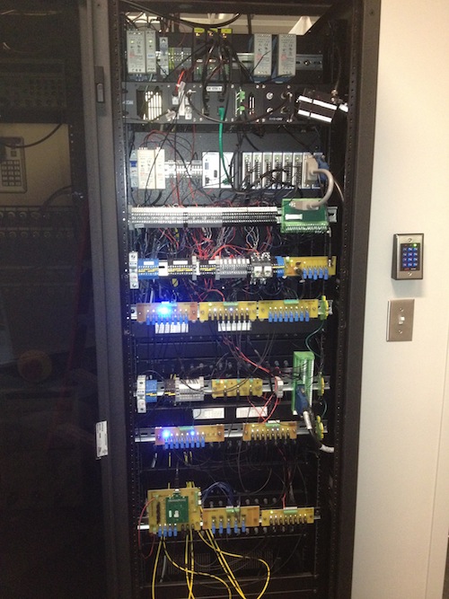
Figure 4: The interlock safety system is controlled by a single NI CompactRIO that monitors over a hundred input and output channels.
Similarly, the pulsed power system requires a complicated sequence of events that must be executed with precise timing. A human controller would have to manually trigger over 20 events (open/closing of relays, power supplies, and switches) with high repetition, which is neither reproducible nor safe over long periods of time. Furthermore, the pulsed power is composed of 20 capacitor banks (see Figure 5) that must be monitored in real-time to microsecond precision every shot to check for dangerous or incorrect behavior and to report the status of charging and discharging. We accomplished this using a cRIO and several digital and analog I/O cRIO modules. The versatility of the FPGA and LabVIEW FPGA once again allowed us to quickly program complicated statements that reliably execute charging events with low timing jitter, check for improper behavior from hardware and - crucially - take appropriate action automatically, and relay the pulsed power status to monitoring software through shared variables. Just as importantly, LabVIEW FPGA allowed us to quickly prototype the pulsed power FPGA code and to discover and correct potentially dangerous bugs.
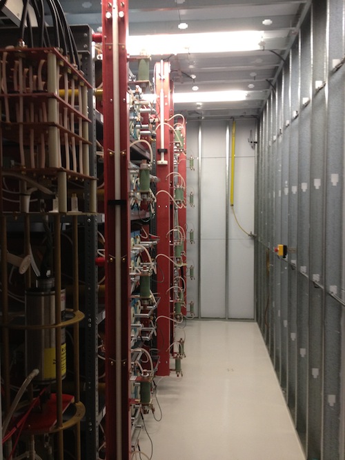
Figure 5: The pulsed power room for the Raptor laser consists of 20 capacitor banks that store 500 kJ of energy. Switches, relays, and power supplies must be controlled with precise timing during a shot.
In addition to the interlock and pulsed power systems, we generally use cRIOs for important but non-critical laser functions, like adding remote control capabilities to a wide range of diagnostic instruments. For example, by running the power lines for GIGE cameras through digital I/O modules, we are able to turn the cameras on and off as they are needed in imaging software. By adding FIFOs to our FPGA programming, we were able to create "RIO" scopes that can monitor laser pulse characteristics and laser energies in real-time, critical for diagnosing the laser during shots, without using valuable high-performance scope channels.
The Phoenix Terminal System
To display information relayed from cRIOs and other hardware components, and to control non-critical or manually oversee critical aspects of the lasers, we created a custom LabVIEW interface known as the Phoenix Terminal System (PTS). The PTS is a networked collection of individual terminal applications that run on multiple computers. Each terminal is identical, capable of spanning multiple screens, touch-sensitive, and acts like a custom operating system for laser programs. Because a terminal can host any collection of laser programs, which can communicate with each other through shared variables, we can control any aspect of the laser from any location in the lab (useful when aligning the laser in the laser bay but monitoring shots in the control room, see Figure 6). By utilizing many features of LabVIEW, such as its comprehensive development environment, support on Windows and Mac, extensive driver support, and highly customizable front panels, we were able to create a modular and scalable application with a Star Trek LCARS-inspired design theme.
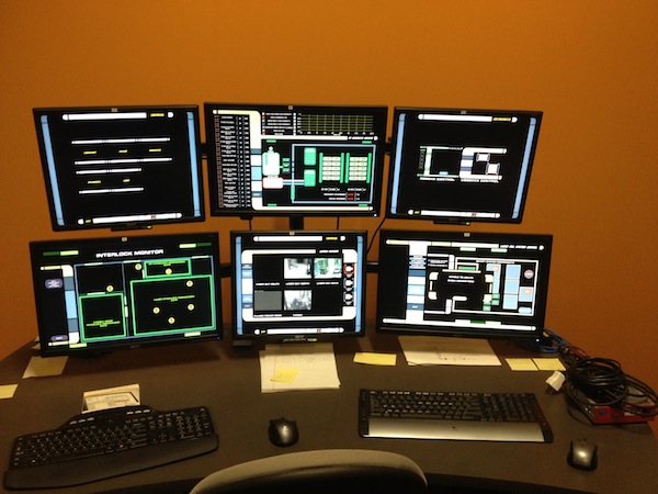
Figure 6: Data from throughout the lab is routed by shared variables to the control room for monitoring.
The core of the software system is LabVIEW's extensive instrument driver support. To diagnose and run non-critical components of the lasers, we use a wide range of scopes, timing boxes, cameras, motors, and gauges. Several instrument classes like GIGE cameras and motors are easily communicated with using built-in LabVIEW drivers found in the NI Vision Development module and NI Motion Assistant. Many other instruments are supported by third-party drivers. Where neither was applicable, it was straightforward to create custom drivers using NI VISA. NI VISA was especially important in allowing us to configure the vast majority of our instruments to run remotely.
While hardware integration is a key advantage of LabVIEW and critical to our control system, the LCARS-inspired interface is its most visible component. While constraining in some respects, the LCARS design theme unifies many disparate programs and provides a guiding principle for organizing and displaying information. The interface extensively leverages the customizability of front panels in LabVIEW, allowing us to create a consistent design theme at all levels of the application. Basic frame elements that border each window were created in PowerPoint and imported as images into custom button controls. Other standard controls, such as numeric, string, array, or cluster, were similarly modified to be consistent while providing standard functionality. Front panels themselves were setup as borderless windows with black backgrounds, and widespread use of window resizing and positioning gives the illusion of a self-contained operating system. Since LCARS has no provisions for menu bars or popup windows, we made extensive use of subpanels to replicate their functionality. The end result is a whimsical, yet functional custom interface (see Figure 7).
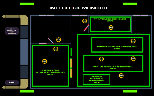
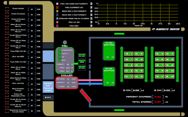
Figure 7: Examples of LCARS-inspired monitoring programs from the Phoenix Terminal System.
Summary
LabVIEW, LabVIEW FPGA Module, and NI Compact RIOs have been critical to the implementation and success of a sophisticated and comprehensive laser control system. We are now able to safely, remotely, and reliably operate the lasers from alignment to high-energy shots while viewing hundreds of data channels in real-time. The extensive instrument support in and customizability of LabVIEW, and the familiarity and abstraction of LabVIEW FGPA, allowed us to create this system from scratch in a fraction of the time that would have been required by custom hardware or other programming languages.
Nominate Your Professor: (optional)
<insert nomination. Does your professor use LabVIEW or other National Instruments technology to make learning difficult concepts engaging, interesting, and fun? If so, nominate him/her as an outstanding educator by telling us who they are, what they teach, and how they make learning a better experience for you.>
- Mark as Read
- Mark as New
- Bookmark
- Permalink
- Report to a Moderator
Cool
- Mark as Read
- Mark as New
- Bookmark
- Permalink
- Report to a Moderator
awesome!
