- Document History
- Subscribe to RSS Feed
- Mark as New
- Mark as Read
- Bookmark
- Subscribe
- Printer Friendly Page
- Report to a Moderator
- Subscribe to RSS Feed
- Mark as New
- Mark as Read
- Bookmark
- Subscribe
- Printer Friendly Page
- Report to a Moderator
Angle of Arrival Detection with NI USRP and LabVIEW Communications
Angle of Arrival Detection with NI USRP RIO
The RF Angle of Arrival (AoA) detection system has been implemented with NI USRP RIO hardware in both LabVIEW 2015 as well as LabVIEW Communications 2.0. The material below is relevent to both of these versions but in order to get these two versions running you need to have LabVIEW 2015 and LabVIEW Communications 2.0 (respectively) installed. For more background on this system, refer to the original AoA Detection System section of this document.
Overview:
This part of the document describes how to implement the RF Angle of Arrival (AoA) detection system from the previous section with NI USRP RIO hardware. This system uses the same direction finding and phase compensation methods and is still capable of detecting up to three transmitting sources.
NI USRP RIO devices have two daughterboards, each with two RF ports, so that they can support twice as many channels as the NI USRP 2920 can. This feature allows users to use two USRP RXs as opposed to four.
This system uses the same methods for correcting USRP phase ambiguities as the previous version did, so there is a reference transmit signal as well as a target transmit signal. The same type of USRP TXs were used in this system for simplicity.
Hardware Configuration:
The following hardware was used to implement this system:
- One PC with a free Gigabit Ethernet port
- Gigabit Ethernet switch
- 2 USRP TXs (NI USRP 2920s were used)
- 2 USRP RIO RXs (an NI USRP 2950R and an NI USRP 2942R were used)
- 5 antennas
- 1 octoclock (with 10MHz reference clock and PPS output)
- BNC splitter T's, cables, and SMA to BNC adapters
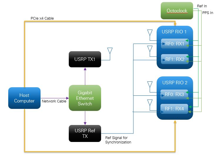
Figure 7: The AoA Detection System with USRP RIO Hardware Setup Diagram
- Connect one antenna to the USRP that is going to serve as the target transmitter (NI recommends using RX1/TX1 port for simplicity).
- Connect one antenna to each of the four USRP RX ports on the USRP RIO devices that are going to serve as the receiver (NI recommends using RX1/TX1 port for simplicity).
- All four receiving antennas should be exactly half a wavelength (of the carrier frequency used) apart.
- Connect both of the USRP RIOs to the octoclock to receive the reference signal and the PPS signal.
- Physically wire the RX1/TX1 port of the USRP Ref TX to all four of the RX2 ports on the USRP RIO devices.
- Connect the two USRP 2920s directly to the Gigabit Ethernet Switch with appropriate gigabit Ethernet cable.
- Connect Gigabit Ethernet Switch to the host.
- Connect the USRP RIOs to the host via PCIe x4. Make sure that the USRP RIO PCI cards are seated securely in the computer. Power up all four USRPs, the octoclock, and the Gigabit Ethernet switch and then power up the host to complete the hardware configuration procedure.
Software Configuration:
The AoA Detection 1st TX Ref Signal.vi and AoA Detection 2nd TX Target Signal.vi function exactly the same as the previous version’s TX VIs. Therefore, the parameters can be set exactly as they would have been in the previous example.
The AoA Detection RX Localization using MUSIC.vi functions exactly as the previous version’s RX VI did. The only difference is that the ‘Device IP Array’ was replaced with a single ‘Device Names’ control for simplicity. The user can enter in the names of the two USRP RIO RXs devices separated by a semicolon into the ‘Device Names’ control (you can find your USRP RIO device names in NI MAX).The ‘Gain Array’ has also been replaced by a single ‘Gain’ control, which is applied to all four RX channels. The rest of the parameters remained the same as they were in the previous version.
You can run both the TX Vis and the RX VI as you would in the previous version.
Note:
For optimal performance, make sure you have installed a current ethernet driver version and close out of all other programs when running the AoA detection system.
*Original AoA Detection System*
Overview:
This document describes how to set up an RF Angle of Arrival (AoA) detection system using the MUSIC multiple array processing algorithm with NI LabVIEW software and NI USRP™ (Universal Software Radio Peripheral) hardware. After a brief discussion of AoA detection or direction finding and phase compensation method, the paper examines the hardware and software within LabVIEW. The system presented here is capable of detecting up to three transmitting sources simultaneously with appropriate parameter configuration.
This software was provided courtesy of Professor A. Manikas holds the Chair of Communications & Array Processing in the Department of Electrical & Electronic Engineering, Imperial College London with Marc Willerton and David Yates.
Table of Contents
1. What Is AoA Detection and Phase Compensation?
2. Implementing an AoA Detection System
3. AoA Detection System: Hardware Configuration
4. AoA Detection System: Software Configuration
5. Working With the Example
6. Building an AoA Detection System in LabVIEW
6.1Target Transmitter
6.2 Reference Transmitter at the Receiving End
6.3 Receiver
7. Additional Resources
1. What is AoA Detection and Phase Compensation
Angle of arrival (AoA) measurement is a method for determining the direction of propagation of a radio-frequency wave incident on an antenna array. Generally this measurement is made by measuring the difference in received phase at each element in the antenna array.
The operation of any phased array system requires RF local oscillator synchronization and ADC timestamp alignment. In this example the local oscillator synchronization among the NI USRPs is achieved using external reference clock. Timestamp synchronization is achieved using external PPS signal. This works fine in the NI USRPs in terms of effectively eliminating relative phase shift over time. Unfortunately, however, every time an USRP re-tune command is sent there is a new phase ambiguity between the boards. Therefore a calibration procedure is required every time a new measurement is taken.
NI USRP boards have two RF ports for duplex operation. It turns out a second signal applied to the second port couples into the software selected receive channel. An RF signal applied directly to the second RF port of each of the NI USRP boards in the array can thus be used to discover the phase ambiguity without a calibration step. It has to be separable in some way from the target signal. A separate NI USRP board can be used for this purpose. So the steps for phase synchronization are:
- Apply 2 different tones (using SSB-SC AM modulation)
- Filter the signals in software
- Use the RF synchronisation signal to evaluate the channel phase offset among different receive antennas
- Align the target signals in phase and gain
- This effectively eliminates gain and phase uncertainties between channels due to the NI USRP boards
After the NI USRPs are synchronized in terms of phase and gain, Multiple Signal Classification (MUSIC) algorithm is used for detecting the AoA of the received signal.
2. Implementing an AoA Detection System
The AoA detection system described here uses a new approach to eliminate phase and gain uncertainty among the USRPs at the receiving end. A separate NI USRP is used to eliminate these uncertainties. After the phase synchronization is achieved, MUSIC algorithm is used to determine the location of the transmitting NI USRP. The overall system including the hardware and software configuration along with a working example is presented below:
3. AoA Detection System: Hardware Configuration
You need five NI USRP transceivers for an AoA detection system. The following configuration is recommended:
- One PC with a free Gigabit Ethernet port.
- Gigabit Ethernet switch
- 6 USRPs (NI USRP-2920 were used in our experiment)
- 5 antennas
- 1 external OCXO based 10MHz reference clock with PPS output
- BNC splitter T's, cables, and SMA to BNC adapters
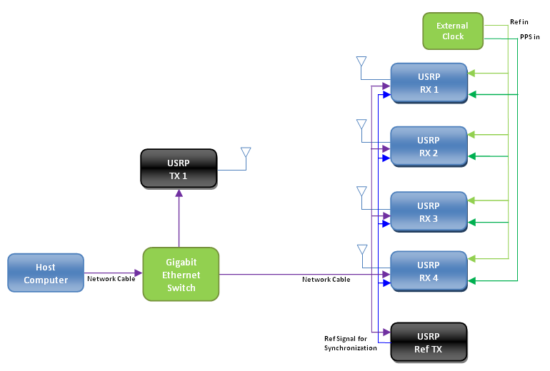
Figure 1: The AoA Detection System Hardware Setup Diagram
Figure 1 shows the configuration you can use for this AoA detection system. The detailed configuration procedure to set up the direction finding system is given here:
- Connect one antenna to the USRP that is going to serve as the target transmitter (NI recommends using RX1/TX1 port for simplicity).
- Connect one antenna to each of the four USRPs that are going to serve as the receiver (NI recommends using RX1/TX1 port for simplicity).
- For desired operation, the all the four receiving antennas should be exactly half a wavelength (of the carrier frequency used) apart.
- Connect all the four USRPs of the receiving side to the external clock to receive the reference signal and the PPS signal.
- Physically wire the RX1/TX1 port of the USRP Ref TX to the TX2 port of all the four USRP RX devices. This USRP Ref TX will provide the signal that the USRP RXs are going to use for eliminating the phase and gain uncertainties.
- Connect all of the 6 USRPs directly to the Gigabit Ethernet Switch with appropriate gigabit Ethernet cable.
- Connect Gigabit Ethernet Switch to the host.
- Power up all six USRPs, the external clock, and the Gigabit Ethernet switch to complete the hardware configuration procedure.
4. AoA Detection System: Software Configuration
This Angle of Arrival Detection example is a LabVIEW application that requires the following software components:
- NI LabVIEW Version 2011 (or later) system design software—Full, Professional, or Student Edition
- NI-USRP Version 1.1
- NI LabVIEW Modulation Toolkit Version 4.3.1
- AoA Detection Example VIs
5. Working with the Example
Unzip the associated zip file to a new folder. Make sure that the location of the folders that contain the MathScript files are included in the MathScript Search Path list. The process of including the folder location in the search path list is given bellow:
- Open LabVIEW
- Select Tool>Options
- Under the Category list, select MathScript
- On the "Search Path" panel include all the folder locations that contains the MathScript files used in this example.
Once the search path is set, open the file entitled AoA Detection 1st TX Ref Signal.vi, AoA Detection 2nd TX Target Signal.vi, and AoA Detection RX Localization using MUSIC.vi in LabVIEW.
The front panel of the AoA Detection 1st TX Ref Signal.vi and AoA Detection 2nd TX Target Signal.vi (Figure 2) contains the parameters for the NI USRP transceivers that are used for both the transmitters. Set the controls of these parameters with the following guidelines in mind:
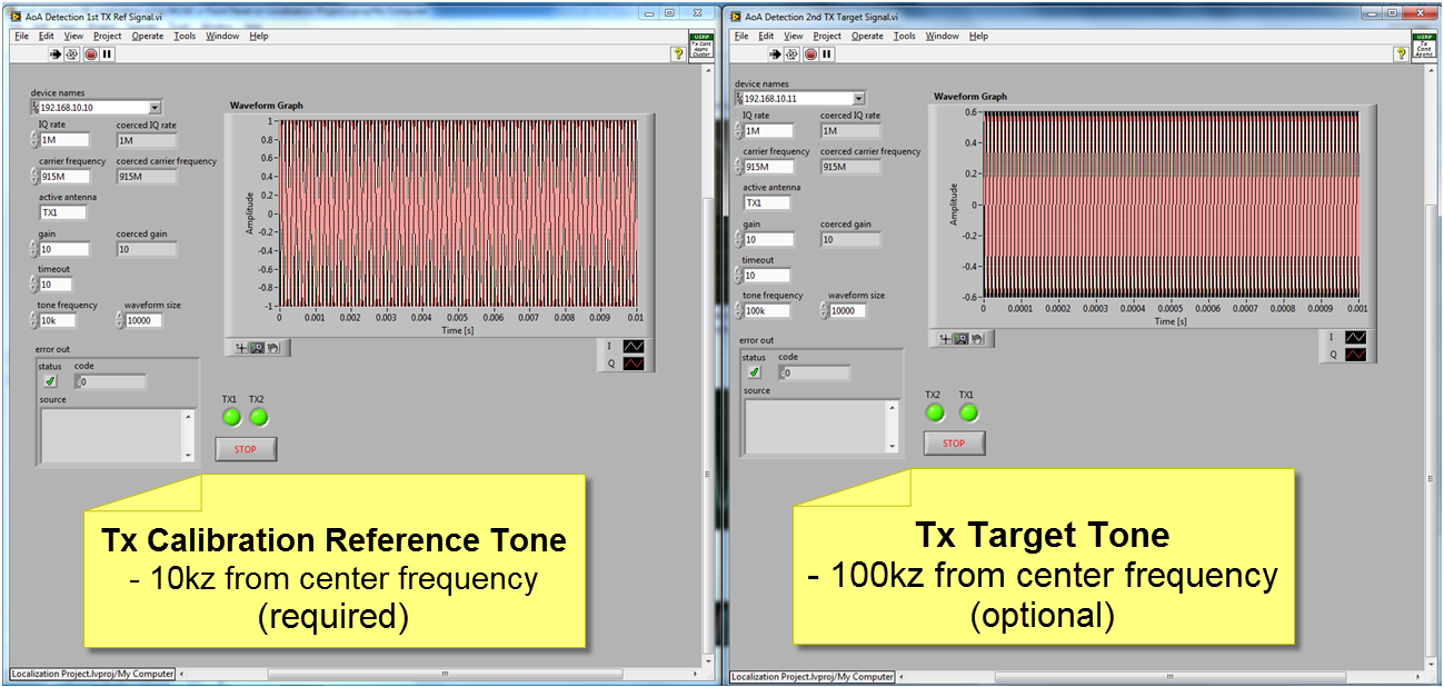
Device Names: Enter the IP addresses associated with the USRP TX1, and USRP Ref TX.
Active Antennas: Enter the appropriate antenna ports TX1 or TX2 that you connected the antennas to each of the devices. For the transmitters in the example, we connected all the antennas to the TX1 port of the devices.
I/Q rate [S/sec], and carrier frequency [Hz]: For the I/Q rate, and carrier frequency enter the sample rate, and the carrier frequency. These parameter values have to be the same for both the transmitter and receiver.
timeout: timeout specifies the time to wait in seconds, before returning an error if the requested number of samples have not been generated. A negative value indicates to the driver to wait indefinitely.
tone frequency: tone frequency specifies the frequency of the transmitted signals. In this example we have chosen 10 KHz for the USRP Ref TX and 100 KHz for the USRP TX1.
- The front panel of the AoA Detection RX Localization using MUSIC.vi (Figure 3, and Figure 4) contains the parameters for the NI USRP transceivers that are used for the receiver. Set the controls of these parameters with the following guidelines in mind:
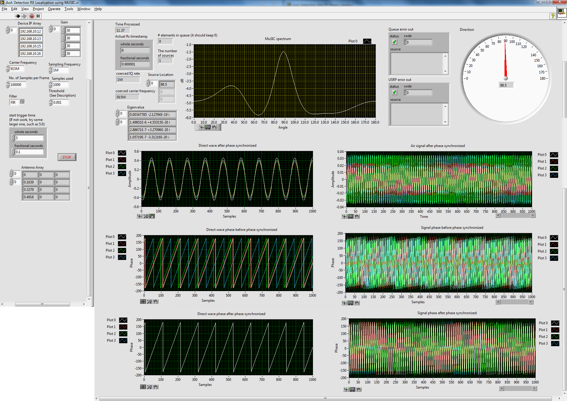
Figure 3: Front panel of the AoA Detection RX Localization using MUSIC.vi
Referring to Figure 4 showing the MUSIC spectrum, it also shows the calibration signal and the target signal after being synchronized, and the phases of these signals before and after the synchronization. The dial on the top right corner presents the location of the target source detected by MUSIC algorithm.
Device IP Array: Enter the IP addresses associated with the USRP RXs.
Gain: Enter the appropriate gain values for all the USRP RXs. For the receiver in the example, we used a gain of 30 for all the USRP RXs.
Sampling Frequency and carrier frequency: For the Sampling Frequency and carrier frequency enter the sample rate and carrier frequency. These parameter values have to be the same for both the transmitters and the receiver.
Threshold: Threshold specifies the threshold to which the receiver compares the received signal strength to detect the presence of the transmitted signal. The value of this parameter depends on the distance of the transmitter.
Filter: This parameter offers you to choose between a FIR implementation and an IIR implementation of low-pass and high-pass filters. These filters are used to separate the target signal from the USRP TX1 and the signal from the USRP Ref TX which is used for calibrating the phase uncertainty among the USRP RXs. In this example, an FIR implementation is used.
start trigger time: Configures the start trigger generated by the onboard device timer and specifies the time to start the trigger. In case of multiple synchronized devices, all of them must use a Start Trigger.
With the parameters set appropriately, you can run both the TX Vis and the RX VI. Doing so; the AoA Detection 1st TX Ref Signal.vi and AoA Detection 2nd TX Target Signal.vi start to continuously transmit the calibration signal and the target signal. The AoA Detection RX Localization using MUSIC.vi upon receiving the signal performs the phase and gain uncertainty elimination using the calibration signal and then uses MUSIC algorithm to detect the AoA of the target signal. The MUSIC spectrum, the phase synchronized signals, and their corresponding phases are also displayed in the AoA Detection RX Localization using MUSIC.vi.
6. Building an AoA Detection System in LabVIEW
This section describes the key components of the AoA detection system:
6.1 Target Transmitter:
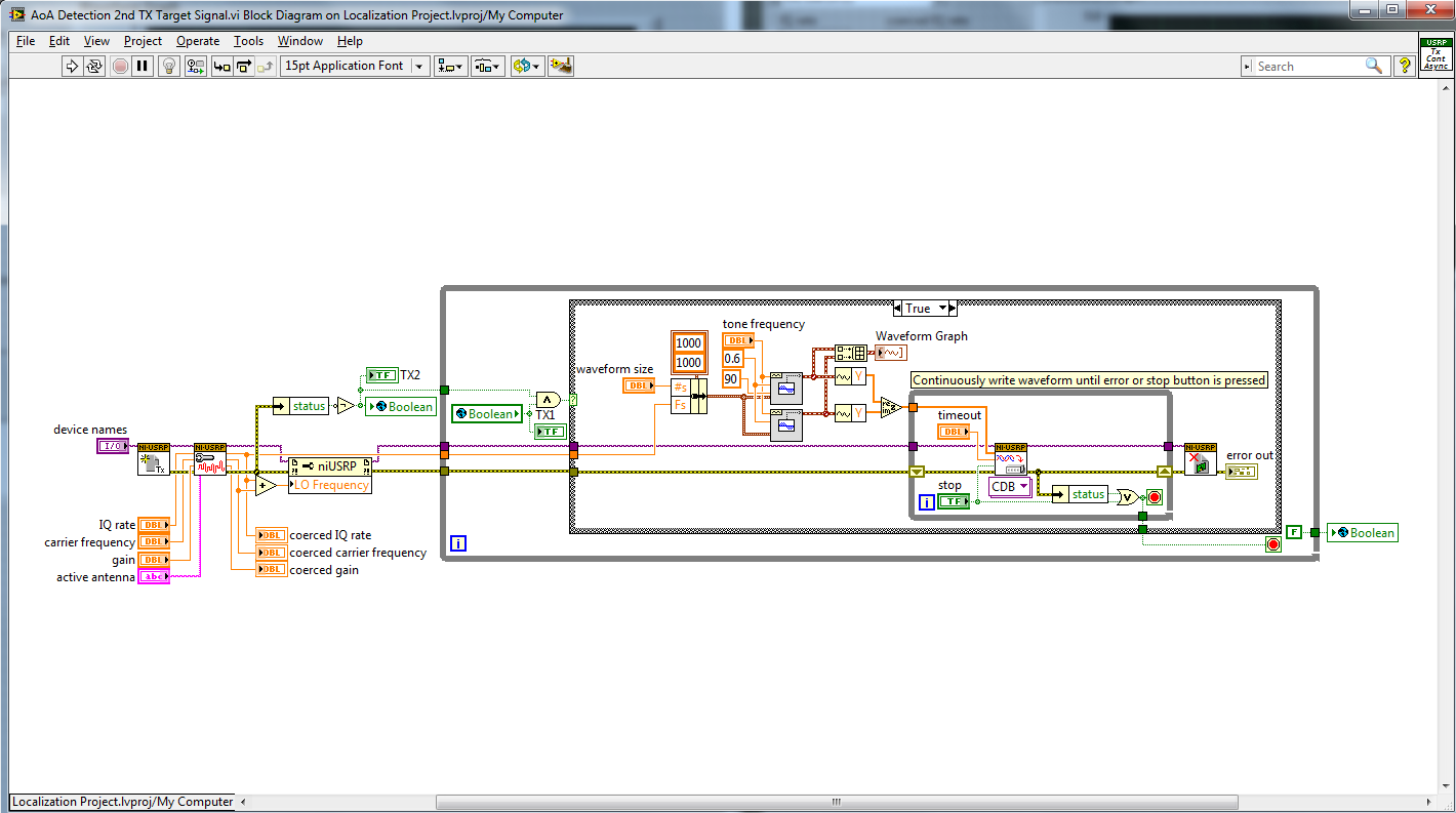
Figure 4: Block diagram of the AoA Detection 2nd TX Target Signal.vi
Figure 4 presents the block diagram of the AoA Detection 2nd TX Target Signal.vi. As can be seen from the block diagram, it opens the target USRP TX session and waits for the other transmitter session to open before performing any further steps. In this example, we have used global variables to make sure both the transmitter USRP sessions are open before they start transmitting. This is necessary if we are trying to initiate multiple USRP transmitters from a single host. The trick is to make sure all the USRP sessions are open and then proceed with transmission. If the transmitter USRP is controlled by a separate host, then we do not need these extra steps. After the VI receives the confirmation that both the transmitter USRP sessions are open, then it starts to continuously transmit a tone of given parameters. This signal is considered as the target signal whose AoA at the receiver is to be detected.
6.2 Reference Transmitter at the Receiving End
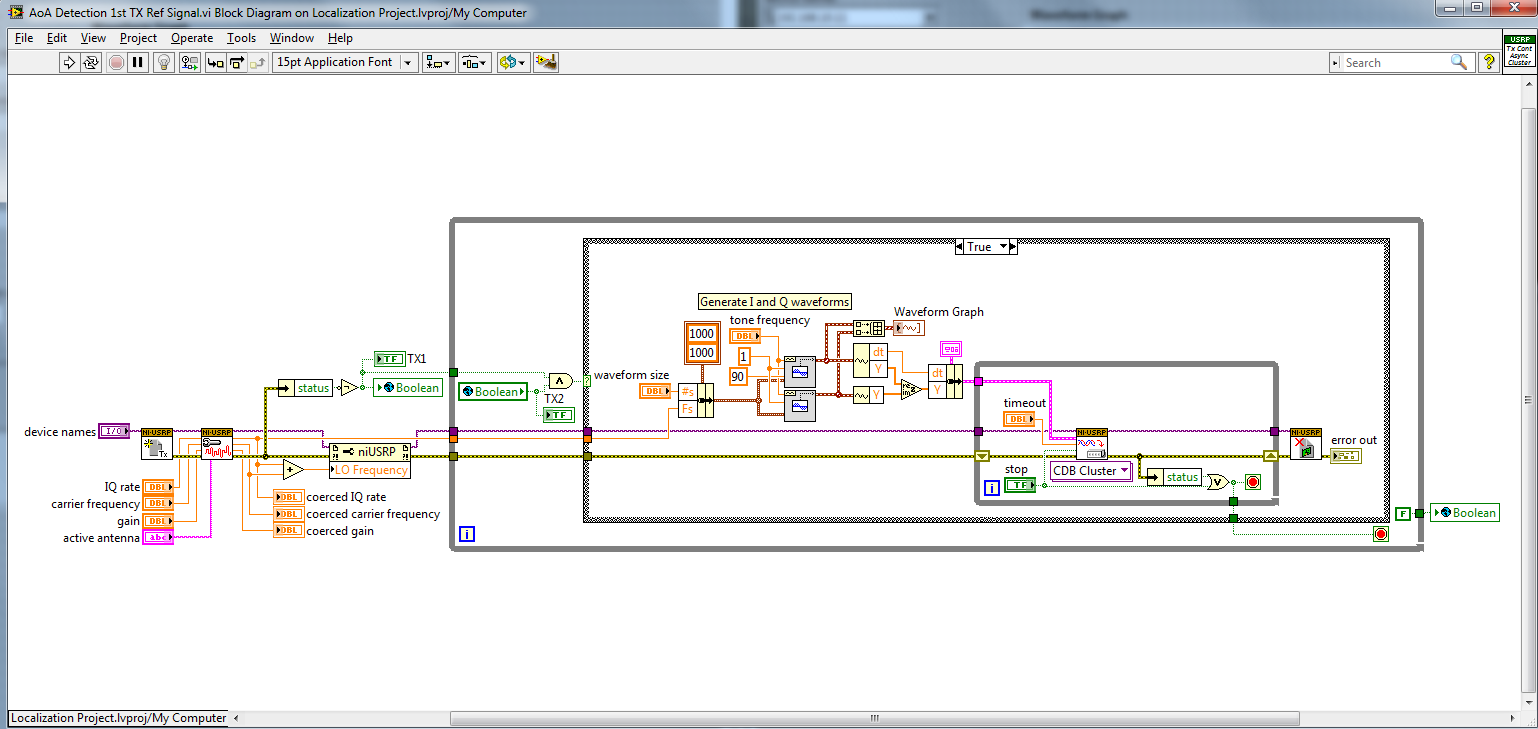
Figure 5: Block diagram of the AoA Detection 1st TX Ref Signal.vi
Figure 5 presents the block diagram of the AoA Detection 1st TX Ref Signal.vi. As can be seen from the block diagram, it opens the calibrations USRP TX session and waits for the other transmitter session to open before performing any further steps. After the VI receives the confirmation that both the transmitter USRP sessions are open, then it starts to continuously transmit a tone of given parameters. This signal is considered as the calibration signal that is being used to eliminate the phase and gain uncertainties among the USRP receivers. To facilitate this calibration process, this USRP Ref TX is physically wired to all the four USRP RXs.
6.3 Receiver:
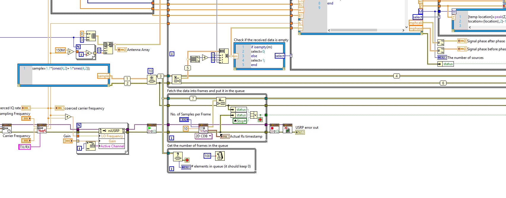
Figure 6 presents the block diagram of AoA Detection RX Localization using MUSIC.vi. The RX VI sets up all the USRPs at the receiver to have the appropriate operating configurations. It first captures a specified number of samples per processing cycle. The RX VI then separates the calibration signal and the target signal using filters as specified by the user. The phase and gain calibration to eliminate the uncertainties is done based on the information provided by the calibration signal. After the target signal is calibrated, it is then fed to the MUSIC algorithm to detect the AoA.
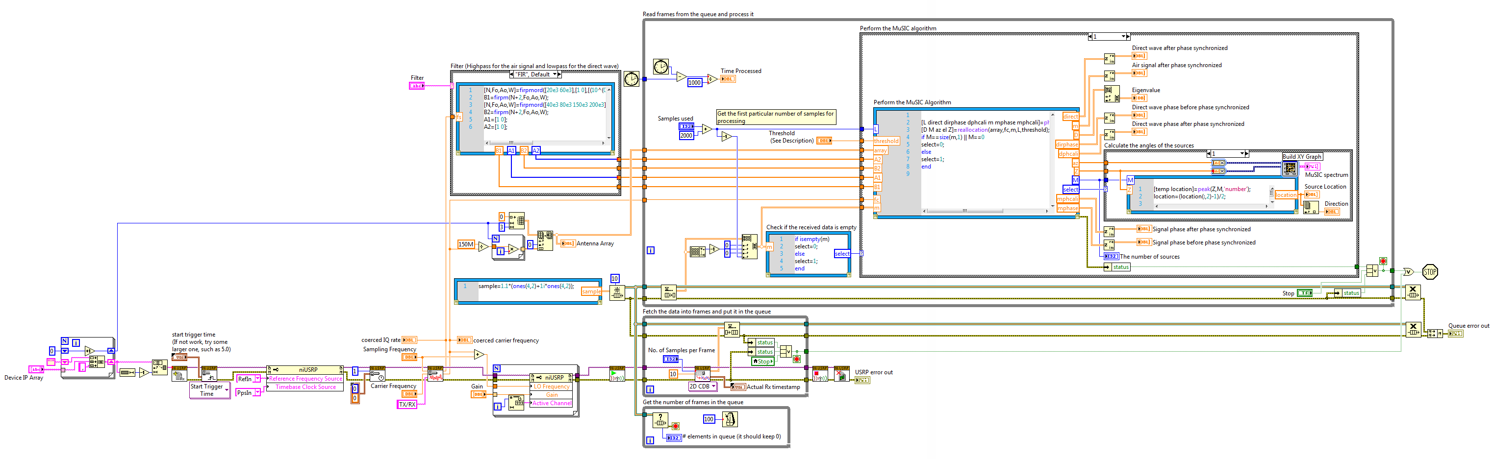
Figure 6: Block diagram of the AoA Detection RX Localization using MUSIC.vi – part 1
7. Additional Resources
- Schmidt, R., “Multiple Emitter Location and Signal Parameter Estimation,” IEEE Transactions on Antennas and Propagation, vol. 34, pp. 276-280, Mar. 1986.
- Manikas, A., Y.I. Kamil, and M. Willerton, “Source Localization using Large Aperture Sparse Arrays,” IEEE Transactions on Signal Processing, 2012, to appear.
- Willerton, M., D. Yates, V. Goverdovsky, and C. Papavassiliou, “Experimental Characterization of a Large Aperture Array Localization Technique Using an SDR Testbench,” Wireless Innovation Forum Conference on Communications Technologies and Software Defined Radio (SDR’11-WInnComm), 2011.
- Mark as Read
- Mark as New
- Bookmark
- Permalink
- Report to a Moderator
Great example
- Mark as Read
- Mark as New
- Bookmark
- Permalink
- Report to a Moderator
I want to know input parameter to apply this example to USRP 2921 model.
Also, I want to know how we Physically wire the RX1/TX1 port of the USRP Ref TX to the TX2 port of all the four USRP RX devices
- Mark as Read
- Mark as New
- Bookmark
- Permalink
- Report to a Moderator
The USRP 2921 is only half duplex (can not TX and Rx at the same time). so
an additional device will be needed to provide the reference tx signal.
We were pretty low tech using SMA to BNC cables and then BNC splitters to
send equal length signals from our master USRP to each of the direction
finding receivers.
Did you see the youtube video?
https://www.youtube.com/watch?v=qBvpllCqDR0
Regards,
Erik
- Mark as Read
- Mark as New
- Bookmark
- Permalink
- Report to a Moderator
Can I realize this example using USRP 2921 with 4 way power splitter to transmit reference tx signal?
- Mark as Read
- Mark as New
- Bookmark
- Permalink
- Report to a Moderator
That should work fine.
- Mark as Read
- Mark as New
- Bookmark
- Permalink
- Report to a Moderator
USRP 2921 model has different frequency band compared to 2920 model.
You set the carrier frequency 915MHz, and sampling frequency 1MHz.
What is the proper carrier frequency and sampling frequency for 2921 model?
- Mark as Read
- Mark as New
- Bookmark
- Permalink
- Report to a Moderator
Hi kdg26, I think you should use the same carrier frequency as your transmitter frequency, as long as it falls in the central frequency range supported by 2921. As to the sampling rate, I suppose you can keep the same settings.
- Mark as Read
- Mark as New
- Bookmark
- Permalink
- Report to a Moderator
I know that 2920 model in this example and 2921 model have different frequency band.
Nevertheless, can I use the same carrier frequency and same sample rate as shown this example?
I suppose that using 2GHz~3GHz or 4.5GHz~5GHz in 2921 model.
- Mark as Read
- Mark as New
- Bookmark
- Permalink
- Report to a Moderator
I want to know whether we conduct this example without Reference TX.
- Mark as Read
- Mark as New
- Bookmark
- Permalink
- Report to a Moderator
FIR filter cannot be implemented. can you tell me the reason why this case occur?
- Mark as Read
- Mark as New
- Bookmark
- Permalink
- Report to a Moderator
If you are using the code, be sure to set the math script search path. If that is not the issue can you share the exact error message and describe how and when it occurs?
Regards,
Erik
- Mark as Read
- Mark as New
- Bookmark
- Permalink
- Report to a Moderator
Erik,
Can you create a copy of the project with the MathScript nodes replaced by MATLAB script nodes?
Thanks!
- Mark as Read
- Mark as New
- Bookmark
- Permalink
- Report to a Moderator
I recommend sing mathscript. You can download the toolkit and use it in 30 day evil mode.
Regards,
Erik
Sent from mobile device.
- Mark as Read
- Mark as New
- Bookmark
- Permalink
- Report to a Moderator
Hi, ErikL. In AOA localization detection vi., the coerced IQ rate and coerced frequency are shown to be zero. I assumed that this problem occurs filter and other block error(include this parameter). we use the 2921 model. this problem related to the input carrier frequency and IQ rate or usrp model? why this problem occur?
- Mark as Read
- Mark as New
- Bookmark
- Permalink
- Report to a Moderator
Also, the error code is shown below:
A runtime or configuration error occurred.
Code: 972
Details: AssertionError: assertion failed:
TX/RX is not a valid xcvr antenna name.
possible values are: [J1, J2].
TX/RX block is right???
- Mark as Read
- Mark as New
- Bookmark
- Permalink
- Report to a Moderator
Coercion to zero is likely due to another error.
Antenna names for NI USRP users are published on the front of the box. If you are building your own using Ettus USRP, names came from the silk screen names on the terminals on the daughterboard itself. The above message sounds correct. I would select J1 or J2... or select the name RX1 or RX2 or TX1 or TX2 (which are the names form the NI USRP-2921.
- Mark as Read
- Mark as New
- Bookmark
- Permalink
- Report to a Moderator
I want to know the reason why coerced frequency and coerced IQ rate are zero.
I just implement your example. I have changed the input carrier frequency to 5GHz. Does it influence this example?
- Mark as Read
- Mark as New
- Bookmark
- Permalink
- Report to a Moderator
um... RG-316 50ohms SMA cable is proper to USRP 2921?? I use the 4-way power splitter (2GHz~6GHz) and 5 SMA cable to connect the reference tx port 1 to port 2 of 4 usrp corresponding receive antenna. is it correct method???
- Mark as Read
- Mark as New
- Bookmark
- Permalink
- Report to a Moderator
What is the proper active antenna name for receive vi block diagram using the port 1 and port 2 at USRP 2921 model.?
- Mark as Read
- Mark as New
- Bookmark
- Permalink
- Report to a Moderator
Hi, ErikL,
Plz explain why [TX/RX] block cannot be implemented in this example.
we should use two port (RX1/TX1 and RX2/TX2) of USRP 2921 simultaneously due to the reference TX signal.
I want to know the proper active antenna name for this case of the example.
I look forward your reply. Thank you
- Mark as Read
- Mark as New
- Bookmark
- Permalink
- Report to a Moderator
Also, why the written sample value ("sample=1.1*(ones(4,2)+1i*ones(4,2))") is used for performing the MUSIC algorithm?
In other words, Why do you use the sample made by Mathscript instead of the real received signal?
Additionally, where is the part of using the reference tx signal in the receive block diagram?
- Mark as Read
- Mark as New
- Bookmark
- Permalink
- Report to a Moderator
Plz reply my comment ErikL~
- Mark as Read
- Mark as New
- Bookmark
- Permalink
- Report to a Moderator
In this example, the receive part 4 USRP use the two port simultaneously, namely, in the 2921 model case, TX1/RX1 and TX2/RX2. What is the proper active antenna name for block diagram corresponding to the receive (AOA detection) vi. file.
- Mark as Read
- Mark as New
- Bookmark
- Permalink
- Report to a Moderator
RX1
- Mark as Read
- Mark as New
- Bookmark
- Permalink
- Report to a Moderator
How can I use the code when I recieving a RF singal from a sensor.?
- Mark as Read
- Mark as New
- Bookmark
- Permalink
- Report to a Moderator
I don't fully understand the question. Direction finding is often the first step in a process. 1. find direction 2. beam form to that location & combine 3. decode . The source of the signal and modulation scheme may affect your detection strategy when isolating the signal you want to find the direction of.
- Mark as Read
- Mark as New
- Bookmark
- Permalink
- Report to a Moderator
Hi,Erikl. I'd like to know what does "antenna arry" mean in figure.3 ? And what does"wavenumber vector" mean in the "fki.m"? Thanks a lot.
- Mark as Read
- Mark as New
- Bookmark
- Permalink
- Report to a Moderator
Hi,Erikl. There is a 4*3array named "antenna arry" in figure 3. could you tell me what is the purpose of it?please answer me.
- Mark as Read
- Mark as New
- Bookmark
- Permalink
- Report to a Moderator
This code was submitted by David Yates of Imperial College. I recommend you contact the research team directly.
- Mark as Read
- Mark as New
- Bookmark
- Permalink
- Report to a Moderator
I am planning to use one 2950 and one 2940 with MIMO cable for 4 channel MUSIC application. I have questions:
- I need high clock and LO synchronization. Two 2950 system or one 2950 plus one 2940 system have the same clock and LO performance?
- if I use 2950 with GPS antenna and connect this 2950 to 2940 with MIMO cable, does it work? or is octoclock-G is necessary?
- In the application above says that:' a calibration procedure is required every time a new measurement is taken.' . do i need this calibration for 2950 and 2940?
thanks.
- Mark as Read
- Mark as New
- Bookmark
- Permalink
- Report to a Moderator
Hi Erik,
I rebuilt your setup using 6 Ettus USRP2. The TX VIs execute flawlessly, but the RX VI would always stop after 20-40 seconds with
"Queue error out: Release Queue in AoA Detection RX Localization using MUSIC.vi".
What's the reason for this? Is the code compatible with Ettus USRP2?
I am looking forward to hearing from you,
best regards, Simon
- Mark as Read
- Mark as New
- Bookmark
- Permalink
- Report to a Moderator
superkeiler, I too am having this issue with USRP N210.
Were you able to find any resolution?
Tim
- Mark as Read
- Mark as New
- Bookmark
- Permalink
- Report to a Moderator
Interesting, It has been a few years (and labview versions) since I ran the code.
If its stopping and giving you the error, that's a good sign.
I would start by figuring out what error is actually kicking out of the While loop. Release queue is something that would run while the program was finishing (i.e. another error had occured and caused the loop to exit.)
Erik
- Mark as Read
- Mark as New
- Bookmark
- Permalink
- Report to a Moderator
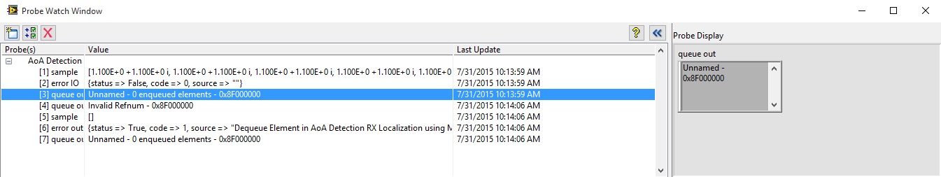
It looks like the error is occurring because the queue is retaining a frame. See attached screenshot - disregard USRP errors.
- Mark as Read
- Mark as New
- Bookmark
- Permalink
- Report to a Moderator
I'm not seeing the spot where the error is being generated. These errors (other than the USRP Error) seem to be falling outside of the while loop. An error outside the loop won't make the program stop on its own.
- Mark as Read
- Mark as New
- Bookmark
- Permalink
- Report to a Moderator
Also, rather than using execution highlight I recommend running it realtime and using probes or indicators to see errors. My guess is that USRP is underlfowing or some other error is creating the errors you are seeing.
Erik
- Mark as Read
- Mark as New
- Bookmark
- Permalink
- Report to a Moderator
- Mark as Read
- Mark as New
- Bookmark
- Permalink
- Report to a Moderator
I figured out the issue. My time source did not have a GPS lock and was failing to output 1pps. Once I fixed that, the USRPs got lock and the VI was off and running.
- Mark as Read
- Mark as New
- Bookmark
- Permalink
- Report to a Moderator
What time source are you using? I'm using Ettus OctoClock. In the spec sheet it says:
"When the GPSDO is not locked to the GPS constellation, it still provides 10 MHz/1 PPS signals, with accuracy better than 25 ppb."
Shouldn't that be fine?
- Mark as Read
- Mark as New
- Bookmark
- Permalink
- Report to a Moderator
Using probes in realtime I figured out that the error originates from the loop named "Fetch the data into frames and put it in the queue". It is giving the following error:
"Error -1074118610 occurred at niUSRP Fetch Rx Data (2D CDB).vi
Possible reason(s):
The received data is out of sequence. This may be a symptom of overflows due to an inability to maintain streaming at the specified IQ Rate, or rearrangement of packets by an ethernet adapter or network switch."
What could be the reason for this?
- Mark as Read
- Mark as New
- Bookmark
- Permalink
- Report to a Moderator
That is an error we've seen before. Its related to your ethernet port. I recommend you install the latest manufacturer driver for the Ethernet Network Interface Card (NIC) and disable 'energy efficient ethernet'. Those solve this in most cases.
- Mark as Read
- Mark as New
- Bookmark
- Permalink
- Report to a Moderator
Hi Erik, I installed the latest driver for my 'Intel 82579LM Gigabit Network Connection' and deactivated EEE in the settings.
Unfortunately, Error -1074118610 still occurs randomly after ~20-90 seconds. I also tried LabVIEW 2011 instead of 2014, with no difference.
Do you have any further hints?
- Mark as Read
- Mark as New
- Bookmark
- Permalink
- Report to a Moderator
The error is coming from the ethernet connection between the USRP and the
computer. The Ethernet card and its connection to the pc and windows are
the critical piece here. Its not Labview so the version should not affect
the result.
Its possible the newer versions of NI-USRP driver are more sensitive. I
have in the past maxed out both NIC input and output buffers and disabled
interrupt moderation with some luck within the pc's ethernet driver.
It it possible to try a desktop pc or install a different or additional
Network card?
Erik
- Mark as Read
- Mark as New
- Bookmark
- Permalink
- Report to a Moderator
I switched to a PCIe based Intel PRO/1000 GT Network Card instead of the onboard solution and now it's running stable for more than 20 minutes until I stop the VIs.
Thank you very much Erik!
- Mark as Read
- Mark as New
- Bookmark
- Permalink
- Report to a Moderator
I am using an OctoClock-G that is GPS locked but I see that you worked out it was your network card. Odd that we were having the same issue that seemed to be caused by two different things.
Glad you got it worked out.
- Mark as Read
- Mark as New
- Bookmark
- Permalink
- Report to a Moderator
The Octoclock i very rarely the cause of any issue. The problem is usually
that an error is thrown by and underflow and not captured. Then when no
data is generated it creates a cascading set of errors in the rest of the
code causing the reported error to be very different from the source.
This is user contributed code so anyone can improve on it and upload their
working modifications and improvements.
Erik
- Mark as Read
- Mark as New
- Bookmark
- Permalink
- Report to a Moderator
Hello Mr.Erik,
I'll try this configuration but using ESPRIT and Chapon MVDR for the algorithm. I think, I just need to replace MUSIC-mathscript to ESPRIT, am I right ?
Before I start, I see on your video, you used 7 USRP instead of 6 like your paper described. Why ?
One more question. On fig.1 you connected each USRP (Rx-side) directly to switch. Why you still used MIMO cable on your measurement ?
Glad to studying your work.
- Mark as Read
- Mark as New
- Bookmark
- Permalink
- Report to a Moderator
1. yes, I believe alternatives to MUSIC should work as well, although the papers I have read indicate that higher numbers of antennas are desireable. The code should scale but will need some modification
2. 7 USRP's... we just happend to have 1 spare. We only used 4 RX, 1 Calibration, and 1 moving target
3. Octoclock is recommended to share Ref and PPS. MIMO Cable takes care of Ref, PPS, and ethernet to a second USRP... so it reduced cables substantially.
- Mark as Read
- Mark as New
- Bookmark
- Permalink
- Report to a Moderator
Thank you for your reply Mr. ErikL.
Today, I was tried your attachment code and implemented it on USRP N210 (for Tx and Rx) and N2922 (for Tx ref). I reduced the size of Rx from 4 to 2 USRP-Rx and I change Ref signal and PPS In to MIMO cable.
When I used IIR-Filter, this is my error-result :
Queue error out : "Release Queue in AoA Detection RX Localization using MUSIC.vi"
USRP error out :
"niUSRP Open Rx Session.vi<ERR>A runtime or configuration error occurred.
Code: 1440
Details: RuntimeError: fifo ctrl timed out looking for acks"
and, when I used FIR Filter, showed Pop Up message :
and on Highlight execution, the program stopped on FIR block diagram.
Why I meet this error ?
- Mark as Read
- Mark as New
- Bookmark
- Permalink
- Report to a Moderator
I believe some other part of the program is throwing the error upstream.
Probably from the USRP Driver.
