- Subscribe to RSS Feed
- Mark Topic as New
- Mark Topic as Read
- Float this Topic for Current User
- Bookmark
- Subscribe
- Mute
- Printer Friendly Page
setting the analog input voltage range
02-26-2008 04:21 PM
- Mark as New
- Bookmark
- Subscribe
- Mute
- Subscribe to RSS Feed
- Permalink
- Report to a Moderator
02-27-2008 06:21 PM
- Mark as New
- Bookmark
- Subscribe
- Mute
- Subscribe to RSS Feed
- Permalink
- Report to a Moderator
The analog input range is settable only while an analog operation is stopped. If you want to change input ranges while a VI is running, you will need to stop the task, re-configure the input range, and start it again. If you're using the Traditional NI-DAQ driver, this will be considerably more difficult, but since you mention the DAQ Assistant, I'm assuming you're using NI-DAQmx.
The DAQ Assistant doesn't offer channel control inputs, but you can right click on the Assistant and choose to 'Generate NI-DAQmx Code'. This will convert the settings in the DAQ Assistant to the DAQmx API calls it uses. The channel set-up VIs will be placed inside a subVI after the conversion. I recommended moving the set-up VIs in the subVI to the main level VI, removing the now empty subVI, and changing the 'physical channel' constant to a control.
Finally, the VI Logger can create LabVIEW code that will exactly reproduce the VI Logger's behavior. Pages 14 and 15 of the VI Logger manual explains how to do this.
VI Logger User Guide
Please let me know if you need any further clarification 🙂
Joe Friedchicken
NI Configuration Based Software Get with your fellow OS users
[ Linux ] [ macOS ]Principal Software Engineer :: Configuration Based Software
Senior Software Engineer :: Multifunction Instruments Applications Group (until May 2018)
Software Engineer :: Measurements RLP Group (until Mar 2014)
Applications Engineer :: High Speed Product Group (until Sep 2008)
02-27-2008 07:12 PM
- Mark as New
- Bookmark
- Subscribe
- Mute
- Subscribe to RSS Feed
- Permalink
- Report to a Moderator
Hi,
Thanks so much for your help!
I decided to use the lower level DAQ vis instead of DAQ assistant, and that made it much easier to set up a channel selector.
As for the voltage range issue, I was wondering if I should make a subroutine that compares the signal amplitude to the maximum values for the three ranges - once the amplitude exceeds one of the range values, it would stop the task, reset the task's range values, and then restart the data collection. Would something like that work, or do you have any different suggestions?
Lastly, the program that we use for our thermocouples is called 'NI Datalogger' - apparently that is different from VI Logger. I tried to follow the instructions from the VI Logger manual, but they don't seem to apply... Any other ideas? I was wondering if I could set up Datalogger as a sub vi, and if so, how? Of course pasting in the code would be preferable, but whatever works! 🙂
Thanks again! Myra
02-28-2008 03:05 PM
- Mark as New
- Bookmark
- Subscribe
- Mute
- Subscribe to RSS Feed
- Permalink
- Report to a Moderator
02-28-2008 05:28 PM
- Mark as New
- Bookmark
- Subscribe
- Mute
- Subscribe to RSS Feed
- Permalink
- Report to a Moderator
I'm glad you're using the DAQmx API VIs. They give you a lot more versatility and will give you the power to change your input range while your VI runs. There are a few properties that can be set while a task is running, but none of them relate to analog input. The complete list of run-time settable properites is in the LabVIEW help: VI and Function Reference » Measurement I/O VIs and Functions » DAQmx - Data Acquisition VIs and Functions » Additional Information » Properties Settable at Task Run Time.
At any rate, a subVI could work for your purpose, but you may find a state machine to be better suited. It will give you a more structured approach and could be easier to design. LabVIEW provides a state machine template from the File » "New..." dialog box. Select 'Standard State Machine' under VI » From Template » Frameworks » Design Patterns. Another option is to use a more advanced structure referred to here as an 'Action Engine'.
Action Engines, What are They?
Finally, I misunderstood what you meant when you said 'Datalogger'. The NI Data Logger is a VI distributed as an executable (which is why you can't see the block diagram). It comes with DAQmx Base, is that the driver you're using? Since it's a compiled executable, the Data Logger cannot be used as a subVI, but LabVIEW provides similar and more flexible functionality. I recommend taking a look at the Write to Measurment File Express VI:
Using the Write to Measurement File Express VI
There are also a few other example VIs in the Example Finder under Fundamentals » File Input and Output. The examples here use LabVIEW's File I/O VIs; if the Write to Measurement File Express VI were the "DAQ Assistant" for data files, then the File I/O VIs are the low-level "DAQmx" API. Two to start with would be "Write to Text File.vi" and "Simple Temp Datalogger.vi".
As always, please let me know if you'd like further clarification 🙂
Joe Friedchicken
NI Configuration Based Software Get with your fellow OS users
[ Linux ] [ macOS ]Principal Software Engineer :: Configuration Based Software
Senior Software Engineer :: Multifunction Instruments Applications Group (until May 2018)
Software Engineer :: Measurements RLP Group (until Mar 2014)
Applications Engineer :: High Speed Product Group (until Sep 2008)
03-04-2008 05:19 PM
- Mark as New
- Bookmark
- Subscribe
- Mute
- Subscribe to RSS Feed
- Permalink
- Report to a Moderator
Hi,
Thanks for your response. So far the most helpful example I've found is the "Cont Acq Thermocouple Samples - Int Clock".vi. I'm a bit confused, though - because when we use Datalogger, we can select one channel (which corresponds to two inputs - one from our thermocouple of interest, and the other from the thermocouple at our reference temperature). We are using type T paired thermocouples, so all of our connections are with copper wires. When I try to use the "Cont Acq Thermocouple Samples - Int Clock".vi it prompts you for the CJC temperature.... this is the cold junction compensation, correct? I thought that this would apply if you have your thermocouple wires connected to wires of a different type (at the DAQ board), creating additional junction voltages that you must subtract off.
In our case, I thought that the wiring within the board is also copper, so we wouldn't be creating any additional junctions - is that right?
I'm also not certain if we are doing something different than usual with our thermocouples, in that we are not just using one type T junction - we have two. Am I making any sense?
Thanks! Myra
03-04-2008 05:48 PM
- Mark as New
- Bookmark
- Subscribe
- Mute
- Subscribe to RSS Feed
- Permalink
- Report to a Moderator
Sorry - I wanted to try to clarify more. Our thermocouple arrangement looks basically like Figure 3 in the "Taking Thermocouple Temperature Measurements" tutorial in the developer zone - if you exchange the iron wire for constantan and the other two constantan wires for copper. After reading the tutorial, I'm left wondering how Datalogger takes into consideration the temperature of our reference point. As I said in the last posting, there's no prompt for the cold junction temperature. Previously I had thought that the program would just measure a voltage difference which would tell us how high above the reference point our 'hot' temperature is - but that would only work if thermocouples are linear. Am I understanding this right?
One thing that I hadn't mentioned before (I was afraid it might complicate things even more 🙂 ) is that we actually use two sets of the thermocouples - one that measures a 'hot' temperature and a reference, and the other that measures a 'cold' temperature and hopefully the same reference. On Datalogger, we type in "Dev1/ai0, Dev1/ai1" under physical channel, and it plots the temperatures of the hot and cold sides (at least that's what it's supposedly doing - now I'm really confused and can't understand how that is possible!). Is there some way that the software might be taking into account the reference temperature that I just can't see now? Since I can't see the block diagram, I really don't know.
Myra
03-05-2008 03:35 PM
- Mark as New
- Bookmark
- Subscribe
- Mute
- Subscribe to RSS Feed
- Permalink
- Report to a Moderator
'CJC' is cold junction compensation, and while the traces on DAQ boards are copper, the connectors on terminal blocks aren't. How are you connecting your thermocouples to the DAQ card?
As long as you use the same type of thermocouple for your entire test, you will only need one reference CJC thermocouple. If I understand your description correctly, you're measuring two temperatures. In that case, you'll need three total thermocouples: one for CJC, another for your hot measurement, and a third for your cold one.
I think the simplest approach would be to use MAX (the Measurement and Automation Explorer) to create an Analog Input task to measure your thermocouples. You can set the thermocouple type, the channels to read, the CJC type and even preview how it takes measurements. NI has made a short video (three and half minutes) that shows how to do create a task in MAX. Rather than selecting a generic voltage input, you would choose a temperature input and then thermocouple.
Creating a Task in NI-DAQmx and Using it in LabVIEW
It would also be very helpful to know what DAQ board you're using and which driver you have installed for it.
Joe Friedchicken
NI Configuration Based Software Get with your fellow OS users
[ Linux ] [ macOS ]Principal Software Engineer :: Configuration Based Software
Senior Software Engineer :: Multifunction Instruments Applications Group (until May 2018)
Software Engineer :: Measurements RLP Group (until Mar 2014)
Applications Engineer :: High Speed Product Group (until Sep 2008)
04-30-2008 05:21 PM
- Mark as New
- Bookmark
- Subscribe
- Mute
- Subscribe to RSS Feed
- Permalink
- Report to a Moderator
05-01-2008 09:43 AM - edited 05-01-2008 09:44 AM
- Mark as New
- Bookmark
- Subscribe
- Mute
- Subscribe to RSS Feed
- Permalink
- Report to a Moderator
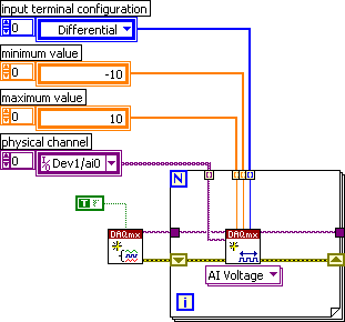
If you mean you could use two different DAQmx Create Channel functions on the same task, then that will not affect sampling. If you mean you could use two different tasks with two different DAQmx Reads, then you can't do that. Shown below is a DAQmx Create Channel inside a for loop so you would have arrays of channels, ranges, configurations, and each can be different.
Also, you should not be placing all of your attached code inside a for loop. There is no reason to be creating, starting, and stopping a task with each iteration. You also mention a sequence structure. You might want o think about ways to eliminate that. Use dataflow to control execution order.
Message Edited by Dennis Knutson on 05-01-2008 08:44 AM
