- Subscribe to RSS Feed
- Mark Topic as New
- Mark Topic as Read
- Float this Topic for Current User
- Bookmark
- Subscribe
- Mute
- Printer Friendly Page
Tilt a boolean square led
Solved!11-15-2017 01:26 PM
- Mark as New
- Bookmark
- Subscribe
- Mute
- Subscribe to RSS Feed
- Permalink
- Report to a Moderator
Hi,
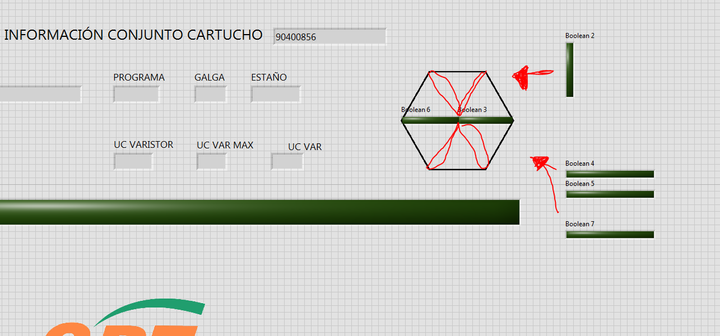
I want to tilt a square led, it seems simply but I do not know how to do it.
I can change the height and widht but no the angle.
I attach a picture where I want to put a led from the center of an hexagon until the perimeter.
Solved! Go to Solution.
11-15-2017 01:36 PM - edited 11-15-2017 01:37 PM
- Mark as New
- Bookmark
- Subscribe
- Mute
- Subscribe to RSS Feed
- Permalink
- Report to a Moderator
Not sure that you can.
One option would be to replace the indicator with a picture ring containing 6 images. 3 angles of OFF and 3 angles of ON.
Make the picture ring's frame transparent, and the unused areas of the image transparent, it should look how you expect.
You can then add the logic to transition between the states as required.
0xDEAD
11-15-2017 01:43 PM
- Mark as New
- Bookmark
- Subscribe
- Mute
- Subscribe to RSS Feed
- Permalink
- Report to a Moderator
Thanks,
Where can I find that picture ring that you say? I do not follow you, I do not understant.
11-15-2017 01:44 PM - edited 11-15-2017 01:53 PM
- Mark as New
- Bookmark
- Subscribe
- Mute
- Subscribe to RSS Feed
- Permalink
- Report to a Moderator
Or use a picture indicator.
You can grab the image of a square led rotate it and place it in the picture as needed.
See this post where Christian showed us how to rotate an image.
You can the image of the Boolean using an invoke node get image.
Ben
11-15-2017 01:58 PM
- Mark as New
- Bookmark
- Subscribe
- Mute
- Subscribe to RSS Feed
- Permalink
- Report to a Moderator
@aitorplaza wrote:
Thanks,
Where can I find that picture ring that you say? I do not follow you, I do not understant.
https://www.youtube.com/watch?v=AmDLCsnOegw
This video shows you how. Make 6 different pictures in the ring and switch between them as needed.
0xDEAD
11-16-2017 08:23 AM
- Mark as New
- Bookmark
- Subscribe
- Mute
- Subscribe to RSS Feed
- Permalink
- Report to a Moderator
11-18-2017 07:20 PM
- Mark as New
- Bookmark
- Subscribe
- Mute
- Subscribe to RSS Feed
- Permalink
- Report to a Moderator
All you need is three different booleans. A rectangular (3,4) and two with the picture of the rectangular LED tilted 60 (2,5) or -60 (1,6) degrees (rotate in a drawing program and import into a button). Now arrange them as outlined with the dashed lines. You can even arrange them in a cluster.
11-19-2017 10:34 AM
- Mark as New
- Bookmark
- Subscribe
- Mute
- Subscribe to RSS Feed
- Permalink
- Report to a Moderator
Of course it also depends what you need this for. If only zero or one LED can be on at the same time (e.g. a direction indicator), you can make a picture ring with 7 images, each containing all LEDs in a single picture. If all LEDs can be ON or OFF independently, you have 64 different states and I would go with my solution above.
11-20-2017 08:18 AM
- Mark as New
- Bookmark
- Subscribe
- Mute
- Subscribe to RSS Feed
- Permalink
- Report to a Moderator
You might also consider using rectangular LED and make an overlay image that has transparent 'windows' with the shape of LED led you would like.
11-20-2017 09:25 AM
- Mark as New
- Bookmark
- Subscribe
- Mute
- Subscribe to RSS Feed
- Permalink
- Report to a Moderator
Here is an example of an overlay (VI attached). I would usually make this a cluster and then typdef it. I would also consider replacing the LED with a color box to allow for more states/colors if needed.


