- Subscribe to RSS Feed
- Mark Topic as New
- Mark Topic as Read
- Float this Topic for Current User
- Bookmark
- Subscribe
- Mute
- Printer Friendly Page
Motor Not Running
Solved!01-23-2012 08:33 PM
- Mark as New
- Bookmark
- Subscribe
- Mute
- Subscribe to RSS Feed
- Permalink
- Report to a Moderator
I am an adult mentor for FRC Team 1553. I am having trouble getting motors to run using the example codes that are part of LabVIEW. We have used LabVIEW for the past several years without anyu problems. We have installed LabVIEW and the three updates (LabVIEW, Utilities, Driver Station.) When I open an example VI, such as simple motor control, I cannot get it to run a motor. We are using a Victor connected to PWM output 1. We are using this years image. We have the NI9403 module in slot 2 of the 8 slot cRIO and a NI9201 module in slot 1. The imaging tool recognizes both of these devices and shows no errors.
We opened the simple motor control example VI and changed the IP address to be for our robot number (10.15.53.2). We can run the VI. Motor won't run by changing the Control that is part of the Front Panel of the VI. I have added a digital input to the VI and wired a switch into that input. We can see that input change state on the Front Panel when we operate the switch with the VI running. I can wire an encoder to other DIs and see encoder work properly on the Front Panel. I can wire a gyroscope to the analog card and see that operate properly on the VI. I added each of these to the simple motor control VI. I added a Motor Get Output VI to the motor line in the code and created an indicator for the Front Panel. We can see the indicating speed change on the Front Panel when we change the speed with the Control on the Front Panel. So, I can see digital inputs, analog inputs, and speed changes. But no motor run.
I made a new FRC cRIO Robot Project with this year's code. I added the motor open and reference to the Begin, added a fixed motor speed of 1.0 in the Periodic Task, and added motor close in the Finish. The Digital Modele and PWM reference were set the same as was done in the simple motor control VI. Running the new robot project on the cRIO and starting the Driver Station software (with Teleop enabled) allowed the motor to run. No hardware was changed between the simple motor control VI above the the new Robot project.
Is there any reason why a motor will not run in an example VI (when other things like digital inputs do work on the same digital input board) but do run in a new cRIO project?
We did have multiple versions of LabVIEW on the computer we are using. When this problem started we removed all versions of LabVIEW and then reinstalled this year's version and all the updates. We even switched all the hardware (NI9403 module, DB37 cable, Digital Side Car) to see if any of those were the problems. None of the hardware was an issue as the motor control works fine in the new Project.
Before removing the old LabVIEW software we reimaged the cRIO to v28 and moved the NI9403 module to slot 4 in the cRIO. We downloaded last year's robot project to the cRIO. Motor control worked fine.
Any suggestions would be welcome as we'd rather not have to use the full Project code just to do a simple test of something.
I have added a simplified version of our simple motor control example. It shows the digital input that was added. The input changes state on the Front Panel when the VI is run and the switch operated to the input is operated.
Paul Sullivan
Solved! Go to Solution.
01-23-2012 09:04 PM
- Mark as New
- Bookmark
- Subscribe
- Mute
- Subscribe to RSS Feed
- Permalink
- Report to a Moderator
When you ran the example, did you also enable the robot with the driver station?
01-23-2012 09:42 PM
- Mark as New
- Bookmark
- Subscribe
- Mute
- Subscribe to RSS Feed
- Permalink
- Report to a Moderator
Thanks for the suggestion. I ran the program and then the Driver Station and Enabled Teleop. Magically the motor ran just fine. Let's say that I was a little disappointed in the amount of time we spent trying to figure this out when the solution was so simple.
Did you read somewhere instructions that you have to run the Driver Station when running an example VI? Maybe I forgot it from last year. But I was really fooled when we ran the VI and the digital and analog inputs operated just fine but the motor would not run.
Thanks for the help.
Time to start doing some programming with the students tomorrow!
01-24-2012 12:01 AM
- Mark as New
- Bookmark
- Subscribe
- Mute
- Subscribe to RSS Feed
- Permalink
- Report to a Moderator
The cRIO disabled outputs unless it is enabled from the driver station for safety. This does not affect the inputs as you noticed, but does affect the PWM, relay, and solenoid outputs.
01-25-2012 10:43 AM
- Mark as New
- Bookmark
- Subscribe
- Mute
- Subscribe to RSS Feed
- Permalink
- Report to a Moderator
Hi,
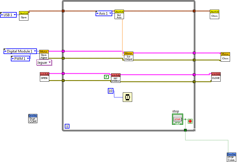
I am having issues with controlling jaguars through the cRIO. I am trying the simple motor control tutorial on Labview (installed on the driver station). I did enable the teleop mode in the driver station but nothing is responding. I am actually trying to fix this unsuccessfully, please can you help and give me the exact steps you used to get this running.
Here is my code:
01-25-2012 10:50 AM
- Mark as New
- Bookmark
- Subscribe
- Mute
- Subscribe to RSS Feed
- Permalink
- Report to a Moderator
The standard things I would check:
-Is your motor plugged into PWM 1?
-If you run in interactive mode (hitting the run button on the VI) can you put probes on the joystick output to see if you are getting values
-Are you outputting values from the digital sidecar-easiest to check with a scope?
-Did you check to make sure your digital sidecar cable is assembled correctly (many teams needed to flip this cable)?
Principal Software Engineer
NI
01-25-2012 11:13 AM
- Mark as New
- Bookmark
- Subscribe
- Mute
- Subscribe to RSS Feed
- Permalink
- Report to a Moderator
-Is your motor plugged into PWM 1?
Yes, i even plugged the jumper aside the PWM output 1.
-If you run in interactive mode (hitting the run button on the VI) can you put probes on the joystick output to see if you are getting values
No, for i am trying without joystick, i am tring to control with a box in the front panel vi.
-Are you outputting values from the digital sidecar-easiest to check with a scope?
How can i do that?
-Did you check to make sure your digital sidecar cable is assembled correctly (many teams needed to flip this cable)?
Can i have a picture with the correct assembly schemes?
Thanks
01-25-2012 11:36 AM
- Mark as New
- Bookmark
- Subscribe
- Mute
- Subscribe to RSS Feed
- Permalink
- Report to a Moderator
Here is information on the cable assembly:http://www.usfirst.org/sites/default/files/uploadedFiles/Robotics_Programs/FRC/Game_and_Season__Info...
I assumed you were using the joystick since thats the code snippet that you posted. Can you post your current code snippet?
To check if the digital sidecar is outputting a pulse train you can just connect the signal pin up to an oscilliscope. You should see a square wave on the PWM 1. If you suspsect an issue with the sidecar I would also try just outputting a digital high on one of the pins. You could verify that with just a multimeter.
Principal Software Engineer
NI
01-25-2012 04:27 PM
- Mark as New
- Bookmark
- Subscribe
- Mute
- Subscribe to RSS Feed
- Permalink
- Report to a Moderator
Thank you Kevin
Flipping the cable for the digital sidecar worked.
02-05-2012 05:48 AM
- Mark as New
- Bookmark
- Subscribe
- Mute
- Subscribe to RSS Feed
- Permalink
- Report to a Moderator
rorim, DO NOT put the jumper on the pins next to the PWM output pins on the digital sidecar! This puts 6V on the PWM pins instead of 5V. The jumpers should only be used if you're connecting servos instead of the Jaguar controllers. They need the 6V instead of the 5V the Jaguars use and you can damage the Jaguar controller if you have the jumpers installed.
