- Document History
- Subscribe to RSS Feed
- Mark as New
- Mark as Read
- Bookmark
- Subscribe
- Printer Friendly Page
- Report to a Moderator
- Subscribe to RSS Feed
- Mark as New
- Mark as Read
- Bookmark
- Subscribe
- Printer Friendly Page
- Report to a Moderator
Unit 0 - Introduction to LabVIEW with MyDAQ: Lesson 2
Introduction
In this video we learn about digital inputs and how to use them in our existing code from Lesson 1
Note that it is highly recommended that you try the exercise problem on your own before watching the solution video. For more information on the key concepts learned in this video look at the links under Additional Resources.
Exercise Problem
Procedure: Create the required VI(s) to achieve the following tasks.
Requirements:
- Modify the program from Unit 0: Lesson 1 so that the loop stops when one of the digital inputs on the MyDAQ is connected to ground.
Exercise Solution Video
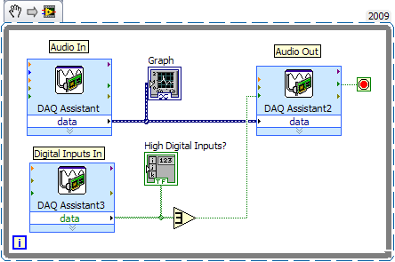
Exercise Snippet
Additional Resources
Arrays: Unit 2 - Fundamentals: Lesson 4
Next Step
- Mark as Read
- Mark as New
- Bookmark
- Permalink
- Report to a Moderator
I'm having trouble getting this program to stop when the input is grounded. The music plays for 60 m sec and then stops without any input. The jumper wire isn't even attached.. The program just stops. I even downloaded the attached program... same result. Does anyone have an idea what I'm doing wrong?
- Mark as Read
- Mark as New
- Bookmark
- Permalink
- Report to a Moderator
Hello,
I'm just trying to make work this easy example, but the inverting port propierty doesn't work like in the video. Actually the voltage in the ports is zero even if are detected like high. My card doesn't work properly? I also try with the attached file, but it uses another acquisition card, why?
- Mark as Read
- Mark as New
- Bookmark
- Permalink
- Report to a Moderator
Hi, don’t invert the DIO pins. And also the wire that is suggested to connect in the GND in this tutorial, connect it 5V (after DGND) instead of GND. connect that 5V connected wire in a bread board. Now run the program. When you connect wire coming from any DIO pins to the point in the bread board that is connected to 5V, the program will stop. Hope this solves the problem and get the teaching this tutorial is supposed to teach. (One can also do the tutorial keeping the pins “invert”. Just you have to do a little change. Think. J)
- Mark as Read
- Mark as New
- Bookmark
- Permalink
- Report to a Moderator
That works just fine. Thank you.
