Description:
In this project a knob (like this: https://www.sparkfun.com/datasheets/Components/TW-700198.pdf) is used to control a counter on the FPGA. If you have problems wiring the knob, have a look at the myRIO Project Essentials Guide!
At first the input signals will be debounced with the debouncer.vi. (May not necessary if proper capacitors are available to debounce the knob on the hardware side!) After that, the Gray-code representation of the rotating direction will be detected in rotaryKnobDriver.vi, which computes the corresponding actions on the counter.
The project also shows how to use the rotaryKnobDriver.vi multiple times, while each instance of the VI operates as a dedicated counter, since the VIs are running in preallocated clone reentrant execution mode.
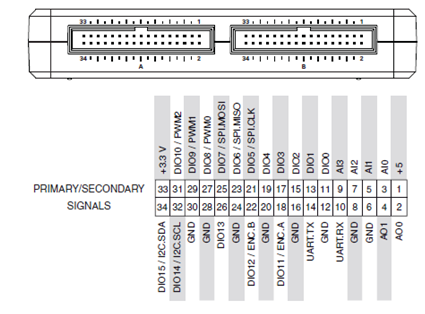
Modified Pin-out:
Pins
Connector A DIO0 – A-signal of the first knob
Connector A DIO1 – B-signal of the first knob
Connector A DIO2 – BUTTON-signal of the first knob, directly connected to the LED0
Connector A DIO3 – A-signal of the second knob
Connector A DIO4 – B-signal of the second knob
Connector A DIO5 – BUTTON-signal of the second knob, directly connected to the LED1
Connector B DIO0 – A-signal of the third knob
Connector B DIO1 – B-signal of the third knob
Connector B DIO2 – BUTTON-signal of the third knob, directly connected to the LED2
Connector B DIO3 – A-signal of the fourth knob
Connector B DIO4 – B-signal of the fourth knob
Connector B DIO5 – BUTTON-signal of the fourth knob, directly connected to the LED3
< If your code is a new FPGA Personality, please add changed pin-outs in either an Excel spreadsheet or by modifying the pictures below>
Code: myKnob_Driver.zip attached
Sunaina K.
Product Marketing Manager for CompactRIO & TSN
Making the intangible, tangible
