- Document History
- Subscribe to RSS Feed
- Mark as New
- Mark as Read
- Bookmark
- Subscribe
- Printer Friendly Page
- Report to a Moderator
- Subscribe to RSS Feed
- Mark as New
- Mark as Read
- Bookmark
- Subscribe
- Printer Friendly Page
- Report to a Moderator
Contact Information
University: University of Southampton
Team Members (with year of graduation): Siyuan Liu (2014)
Project Supervisor: Dr.Soon Xin Ng Michael
Email Address: sl5g12@soton.ac.uk, sxn@soton.ac.uk
Submission Language:
English
Project Information
Title:
Star-QAM Implementation and Investigation in LabVIEW and USRP
Description:
This main objective of this project was to develop and implement a Star-QAM mainly in LabVIEW and USRP and investigate the performance both by it++ in Linux OS and LabVIEW under Windows OS, along with the real-time hardware testing in NI USRP.
Products:
- NI LabVIEW 2013 with Modulation Toolkit and MathScript RT Module
- NI USRP 2920
The Challenge:
Star-shaped quadrature amplitude modulation, short for Star-QAM, is the same as DAPSK (differential amplitude and phase shift keying). It exhibits a low complexity since it dispense with the channel estimation. It was constructed using multiple concentric rings for constellation diagram, which increases the ability in data transmission and reduces the bit error rate, short for BER and improves the performance while transmitting signal messages in comparison to DPSK.
The implementations were done in LabVIEW both for DPSK and DASK part by part. Both of them need to apply a differential modulation, after the mapper in the transmitter part and before the de-mapper in the receiver part. The implementation consist of two major parts, modulation and demodulation. In the modulation part, the signal will be generated and pass through a subVI that will separate the symbol into amplitude and phase bits. Each part will run through a differential modulation and come out with a differentialed output. After multiplying the results, it will then pass through a subVI that will add the pilot symbols in front of the symbols for each transmission. Then it will be upsampled and filtered before the modulation stage is achieved.
The Solution:
The entire design was sectioned in to two stages, DPSK and DASK. Each stage was established individually and within each stage all the subVIs were developed with the corresponding operation. Testing were carried out parts by parts to make sure all the sub-functions can work on its own so after merging all the subVIs the entire design can meet the expectation. Another advantage of performing the experimentation in this way is that, when come to the simulation it will be easier to allocate the bug and do a quick fix.
A 3-bit 8-DAPSK modulation shown in the block diagram Figure 1 was used as an example of the Star-QAM in this session for the illustrating the philosophy. In this case, U_k(2) represents the MSB, which is denoted as b_in(k) in the figure, is the most significant bit of the 3-bit signal and is the carrier signal for amplitude modulation while U_k(1,0) represents the other two bits of the 3-bit, which denote the phase modulation. In this session, DPSK will be explained first followed by DASK and the default example used here is an 8-DAPSK unless stated otherwise.
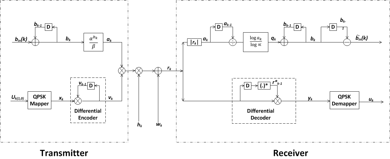
Figure 1: Block diagram of the DAPSK design
Since this project was built part by part, the DPSK module was developed at first. DPSK, which is a traditional modulation scheme that only takes the phase shift into consideration. An 8 Star-QAM was designed for the first stage implementation. The DPSK module was designed in two parts, the modulation and demodulation and both parts will be explained here with details.
As known the main purpose of the differential modulation is to reduce the complexity by omitting the channel estimation at the non-coherent detection. And one thing need to mention here is the reference bit, it needs to be implemented at the beginning of differential encoding and before the mapping frame occurs. The reference bit conveys the information both about amplitude and phase, it sets the initial position in constellation diagram, i.e. where the first message symbol should be placed on the diagram.
Due to the limitation of this form, the detailed deviation for DPSK will be presented below in Figure 2.
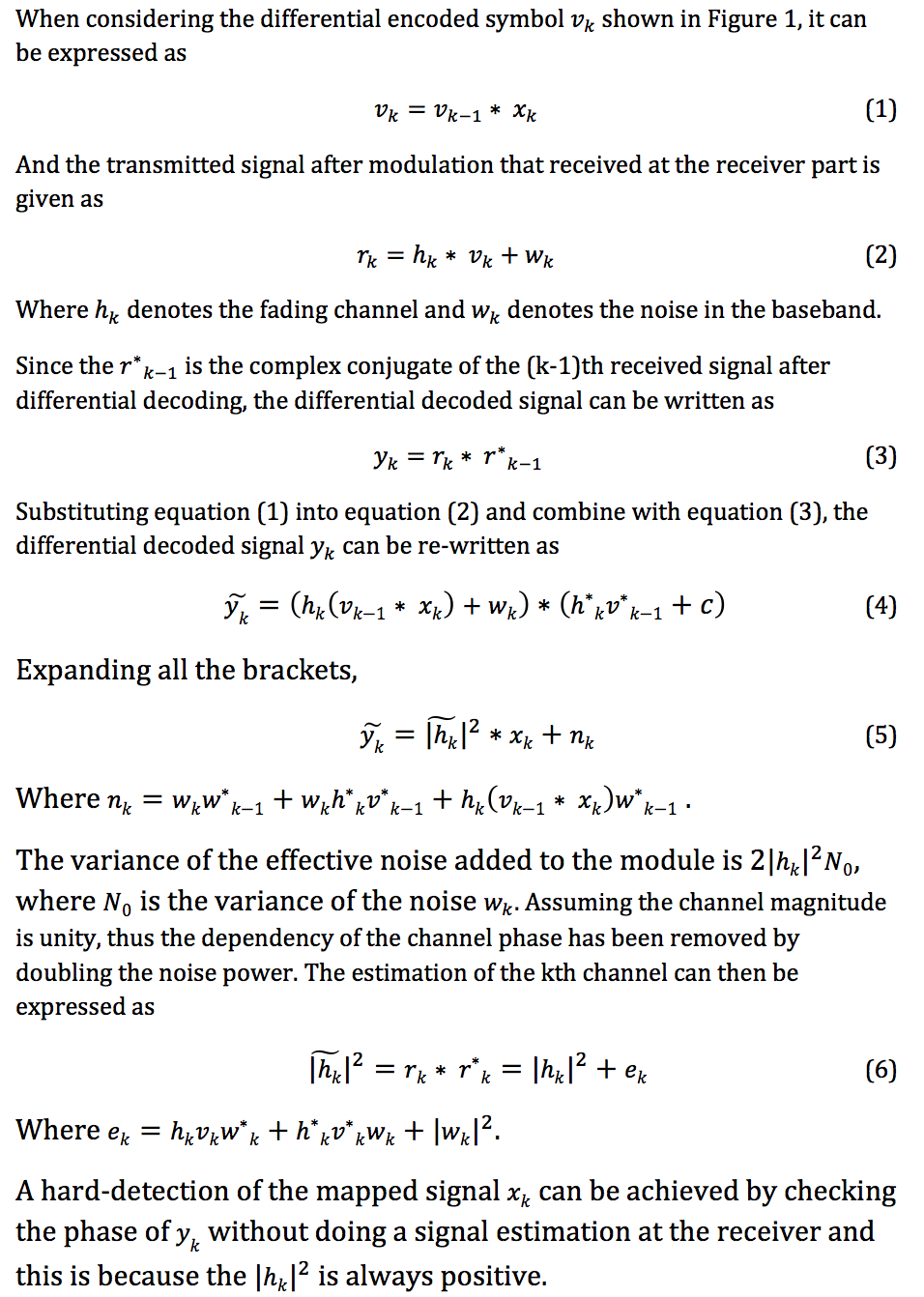
Figure 2: Derivation for DPSK
In Figure 3, a detailed deviation for DASK along with the utilization of the symbol energy used for this project are illustrated.
 Figure 2: Derivation for DASK
Based on the DPSK and DASK that had already been built up, the implementation of DAPSK was achieved by doing a merge of DASK and DPSK. Each module contains two parts, transmitter and receiver. Each part also consists of modulate and demodulate. The demodulate part was cascaded to the modulate part in transmitter construction for simulation purpose. In this session, both transmitter and receiver constructions and optional functionalities will be explained in detail. The investigation of DAPSK using USRP can also be found in this session along with the problems that had conquered. Afterwards, the reason of putting producer/ consumer and the pipelining structures into use for building up the modules will also be outlined in this session. This session will be in two parts, first is the implementation of Star-QAM in NI LabVIEW followed by the Star-QAM investigation using NI USRP.
Similar to what have been done in the modulation module, a demodulation module was designed and developed as shown in Figure 1. After root raised cosine filter and down-sample, the received signal is then checked frame by frame to ensure that the data is demodulated only when it is valid.
The Results
Generally, the project goals were met with the expected simulation results and real time testing results coincided with the simulation results. Most of the workload were completed within the estimated and scheduled time without major delay. The implementations and investigations of the Star-QAM were achieved with the full functionality.
The result can be seen from Figure 4,the transmitter on the right hand side is transmitting a randomly generated signal to the receiver via USPR. The received signal is then being analyzed and demodulated and then plotted. The form of the presentation is as shown in the constellation diagram and eye diagram. The BER is also another parameter can be taken into consideration to validate the success of the project. The BER of this module that will drop to 0, which meets the expectation, is a good sign for data to be transmitted successfully.
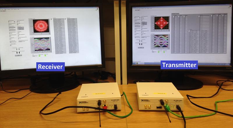
Figure 4: Implementation of Star-QAM using LabVIEW and USRP
Poster
The poster is shown below and can also be found in the attached file.

Nominate Your Professor
The contact information for the supervisor of this project can be found below.
Dr Soon Xin Ng (Michael)
Email: sxn@ecs.soton.ac.uk
Telephone: +44 (0)23 8059 3376
Fax: +44 (0)23 8059 4508
