- Document History
- Subscribe to RSS Feed
- Mark as New
- Mark as Read
- Bookmark
- Subscribe
- Printer Friendly Page
- Report to a Moderator
- Subscribe to RSS Feed
- Mark as New
- Mark as Read
- Bookmark
- Subscribe
- Printer Friendly Page
- Report to a Moderator
SquidROV MkII - Development of Biomimetic ROV
Contact Information
University: University of Edinburgh
Team Members (with year of graduation): Sacha Aichroth (2015), Zedong You (2015), Aysha Feng (2015).
Project Supervisor: Dr Aristides E Kiprakis
Email Address: S.Aichroth@sms.ed.ac.uk
Project Information
Title: SquidROV MkII - Development of Biomimetic ROV
Description: The project continues from the success of SquidROV MkI by developing an upgraded ROV. The ROV uses undulatory fin propulsion, the same method used by a squid and cuttlefish in nature. This method of locomotion is beneficial as it provides a high degree of manoeuvrability with a low turbulence foot print. This has uses navigating silty seabed’s, in wildlife videography and in military applications. The ROV features two undulatory fins which can provide four degrees of freedom and a LiFi coms system for wireless underwater control.
Hardware:
- MyRIO 1900
- 7.4 V, 4250 mAh LiPo battery
- 18 Digital servo motors HS-5646
- L3G4200D three-axis gyroscope
Software:
- LabVIEW 2014
- MyRIO toolkit
- System and control toolkit
- FPGA toolkit
- Xilinx Tools
- Inventor (3D CAD)
The Challenge:
- Design and manufacture a watertight hull and develop a mechanism to undulate a fin using servo motors.
- Design and manufacture a system to control direction yaw.
- Develop a system to control depth.
- Implement all mechanical controls using LabVIEW and a myRIO controller.
- Carry out trials in the Universities wave tank demonstrating all functions and design specifications.
The Solution:
Before manufacture the design was modelled on 3D CAD software, as seen below in Fig 1. This was useful for drafting compenents and for carrying out neutral bouyancy calculations.
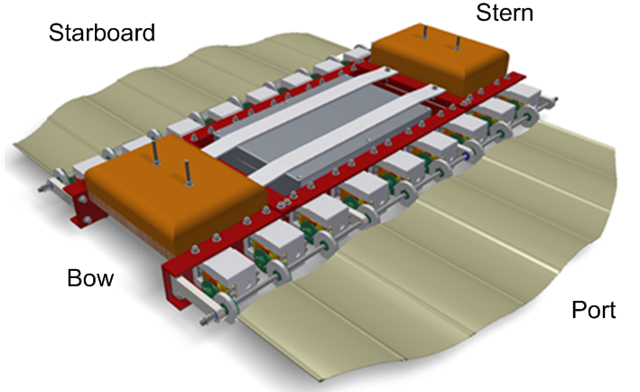
Fig 1: CAD render of the ROV
Powertrain Assembly
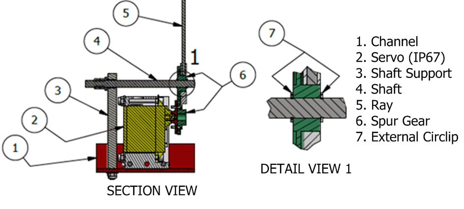
Fig 2: A detailed drawing showing the components of the powertrain assembly. Note: This drawing only details one servo, this assembly is replicated for the 18 servos.
The design seen in Fig 2 uses a servo motor with two spur gears. The shaft supports had to have very tight manufacturing tolerances as these gears could only withstand ±0.2mm of vertical misalignment. With this design all bending moments are transferred from the ray and reacted into the shaft (item 4). This means the bending stress experienced in the servo is eliminated, increasing servo life expectancy.
Fin Design
The fin is fabricated out of waterproof tenting fabric which is 0.3mm thick and made of nylon with an acrylic coating. The fin is designed for two wavelengths along the fin length with amplitude of ±25⁰. The wave profile and governing variables can be seen below in Fig 3.
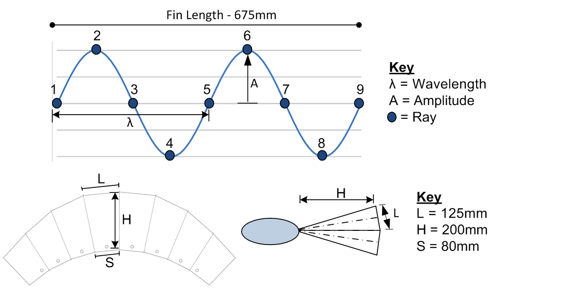
Fig 3: Fin design, showing governing variables and dimensions.
Espen Magnussen, noted from SquidROV MkI that two wavelengths provided the greatest stability to speed ratio as the lateral thrust is cancelled out by having an even number of waves along the fin. It was found that operating with one wave length caused large changes in lateral thrust which created a wobbling effect. Figure 3 also demonstrates how the fin is designed to a specific amplitude and length. The ray creates a larger arc at the tip than at the base and this why the geometry is formed of eight trapezium shaped panels.
The fin is joined to the rays through individually sewn pockets. This means the fin is easy to change and is also strong, as it is made of one piece of continuous fabric.
Electrical Assembly
The ROV has 18 servo motors to individually control. The electrical circuits requires each servo to have power and for the servo signal to be connected to the myRIO controller. The servos are waterproof and depth rated to 1m. However, the battery and myRIO must be protected within a water proof enclosure. The enclosure is rated to 5m depth (IP68).

Fig 4: A schematic showing the electrical circuit with 18 servo motors and how controls were communicated to the myRIO through LiFi to the PC and X-Box controller.
The enclosure is made of aluminum and the lid is sealed with a neoprene gasket and fastened down using stainless steel screws. For the electrical connections to leave the enclosure an Ampseal gland was used. This gland is rated to withstand submersion up to 1m depth and features a double seal which interfaces with a PCB and its opposing plug.
Control
The myRIO features a Xilinx FPGA which has customisable inputs and outputs and an ARM A9 processor capable of handling large volumes of real-time calculation. In order to drive 18 servo motors the default FPGA personality had to be modified. The modification involved adding more PWM loops to additional output ports. Once the FPGA has been finalised the code had to be compiled to create an FPGA bitfile. This requires significant CPU time, so it is done on a National Instruments cloud computer. The file took 40minutes to generate.
For the SquidROV MkII the code was broken down into a number of VI’s as seen below in Fig 5a.
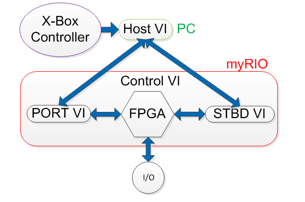
Fig 5a: A schematic showing the structure of the VI’s within the LabVIEW code. The arrows indicate the direction and location of control and indicator flow.
Within the Port and Starboard VI’s there are extensive flow diagrams which program each servos angle relative to one another to create a travelling wave. The basic controls of frequency, wave speed and amplitude have remained unchanged from SquidROV MkI. However the deflection has been altered to allow the ROV to change depth. The host VI can be seen below in Fig 5b.

Fig 5b: A screen shot showing the labVIEW host VI. All variables were controlled using the X-Box controllor. This screen was used to monitor specific variables.
In order to control the ROV a games console controller was used. This provided many easy to use joysticks and buttons which could be programmed into LabVIEW. The fin membrane was designed for two wavelengths with amplitude of ±25⁰. This meant the variables of phase and amplitude were fixed. Wave speed was also fixed however this needed thrust data to establish an optimum value. The controls used can be seen below in Fig 6.
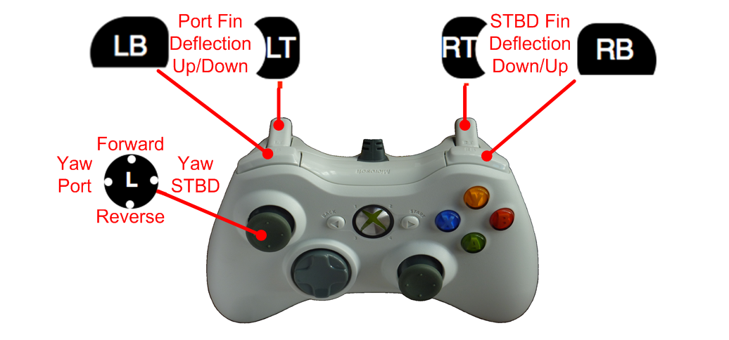
Fig 6: A diagram to show the controls that were assigned to the X-Box controller.
It was important that forward thrust was governed by one control as this meant the phase of each fin would be in time. If each fin was controlled independently like a tracked vehicle, the normal/lateral forces of the thrust would not cancel, potentially causing instability. These controls give the ROV four degrees of freedom; forward/backward, descend/ascend, rotational yaw and rotational roll. Figure 7 below shows how deflection can change the depth of the ROV. The deflection angle is controlled, by manipulating the fin away from the neutral axis.
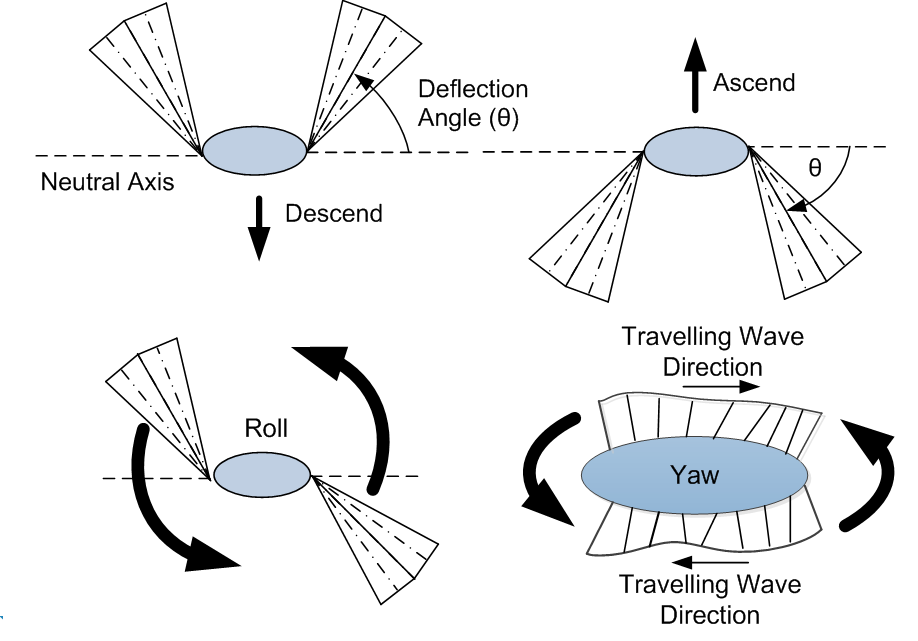
Fig 7:A diagram demonstrating how the ROV can decend, asscend, roll and yaw. Roll is achieved by deflecting the fins in opposite directions. Yaw occurs when one fin is reversed and the other is driven forward.
The ability to control roll will be useful in maintaining the ROV’s horizontal operating plane. Due to the distance between the CB and COG it should not be possible for the ROV to purposely capsize. This is because the fin cannot generate enough thrust to overcome the 1.1Nm stability moment. To initiate a full roll each fin would need to provide 3.5N of thrust, this amount of lateral thrust is deemed optimistic.
Results
Using LabVIEW all the controls were successfully implemented, this allowed the ROV to navigate the tank with four DOFs. During testing the ROV demonstrated its biomimicry as seen below in Fig 8.

Fig 8: A comparison between a Squid and SquidROV MkII swimming from left to right. These photos demonstrate the ROV’s biomimicry.
Yaw was successfully tested and proved to be very effective with a rate of 0.4rads-1. Due to no plan view cameras the pivot point was not possible to detect however through observation it seemed to remain stationary. Once again during this movement the ROV was very stable and remained level.The test showed a forward velocity of 0.3ms-1. This velocity was calculated from the video footage whilst two wavelengths were travelling down the fin. The ROV proved to be very stable operating under these parameters. Furthermore it is very difficult to calculate but visually acceleration seemed instantaneous as well as deceleration.
Buoyancy calculations proved to provide good estimates however it was miscalculated the extra weight generated from the wiring. The wires had to be extensively wrapped in multiple layers of heat shrink and silicon and this added an extra 350g. This meant extra foam had to be added particularly at the stern where the wires terminated into the Ampseal. Despite these complications neutral buoyancy was achieved and the ROV was able to swim with a level orientation.
Video
Level of completion
The ROV is fully functional using a USB wired connection. Lifi integration is yet to be fully field tested.
Time to build
400 hours, part of MEng Thesis, started end of September 2014.
Additional Revisions
Find optimum operating parameters, by attaching the ROV to a calibrated load cell. This experiment is expected to find less than 5N of thrust; therefore a sensitive load cell is required. This data would progress the project and provide the ROV with the best wave speed and phase for a specific fin membrane design. This would then lead onto trialing different fin dimensions meaning the variables of fin height, length and amplitude could be explored for maximum thrust.
By using two fins it is possible to achieve movement in all six DOF’s. Currently the ROV can only achieve four DOFs. The DOF’s not achieved are lateral y-axis movement and rotational pitch. Lateral y-axis movement would be easy to achieve as this would be a standing wave on only one fin. Pitch is more complicated and can be achieved by manipulating the neutral axis into a curve as shown below in Figure 9. A trigonal neutral axis profile could also be used and this could be easier to program however a curve would be more efficient and elegant.
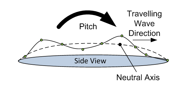
Figure 9: A diagram showing how the rotational DOF of pitch can be achieved by manipulating the neutral axis into a curve.
Relays would enable battery power to be conserved as fins would not be powered during launch and set up. The myRIO could then power up each fin as and when required. A robust design would be needed to ensure power was never lost to the myRIO controller.
To enable the ROV to effectively change depth a variable buoyancy system is recommended. The best system and most widely used for model submarines is the recirculating compressed air ballast system (RCABS). This method has some built in redundancy, in the event of loss of power a capacitor can open the valve causing the ROV to surface. It is estimated a ballast capacity of 200ml would be suitable for SquidROV MkII.
Implementing variable amplitude profiles. Several studies have noted the possible benefits of implementing a CPG which can generate different amplitude profiles. In nature a fish does not use a perfect sine wave. The waves studied by Tianjiang Hu et al show a variable profile and this could prove to be more efficient.
Poster and Software
See attached files Poster.pdf and LabVIEW.zip Code.
Nominate Your Professor
Dr. Aristides Kiprakis has made NI technology available to undergraduate students at The University of Edinburgh. This year seven different projects used myRIO controllers for their master’s thesis and Aristides collaboration with NI and Beejal Shaah (NI Field Engineer) has made this possible. His teaching of Control and Instrumentation now incorporates LabVIEW and myRIOs, meaning each year 130 engineering students are learning the capabilities of NI and its industrial applications. By supervising this project he has made my final year at university very rewarding and his project has vastly improved my engineering skill set. For these reasons, I would like to nominate Aristides as an NI outstanding educator.
- Mark as Read
- Mark as New
- Bookmark
- Permalink
- Report to a Moderator
Excellent project, I follow this project when it was posted in 2014. Really cool...
but the poster (i.e. Poster.pdf 1147KB) is in Chinese, not much related to this wonderful project.
Also, please check if the LabVIEW code.zip belongs to this project, it does not look quite right
