- Document History
- Subscribe to RSS Feed
- Mark as New
- Mark as Read
- Bookmark
- Subscribe
- Printer Friendly Page
- Report to a Moderator
- Subscribe to RSS Feed
- Mark as New
- Mark as Read
- Bookmark
- Subscribe
- Printer Friendly Page
- Report to a Moderator
ROBOTIC GEAR TRANSMISSION
Contact Information:
University: Sri JayachamarajendraCollege of Engineering, Mysore, Karnataka, India.
Team Member(s): Srikanth V, Parvez N Mulla, Puneet R Kulkarni.
Email Address: shrknth@gmail.com, mulla.parvez@gmail.com, puneetrkulkarni@gmail.com
Project Information:
Title: ROBOTIC GEAR TRANSMISSION
Description:
An RGT (Robotic Gear Transmitter) is akit which can be adopted in bikes, to shift the Gears automatically. The RGT isa plug-in device that can be used on any bike, thereby making the bike hybrid with both automatic and manual transmission features.
Products:
LabVIEW, CompactRIO, Module N9505,Module 9215.
The Challenge:
Fed up of shifting gears every secondin the traffic ? Or Does your girl friend want to ride your bike and she hatesshifting gears ? Or have you ever come across a situation where in your friend has an urgency of using your bike and never knows how gears are shifted ?
To any of the above questions if your answer is yes, here is the solution.
RGT is a device that can be attached to any geared two wheeler motorcycle and make it automatic. Not just automatic, precisely hybrid so that the user can shift from Manual to Automatic and vice versa at any moment.
The Solution:
The modus operandi of this embeddedsystem goes like this.
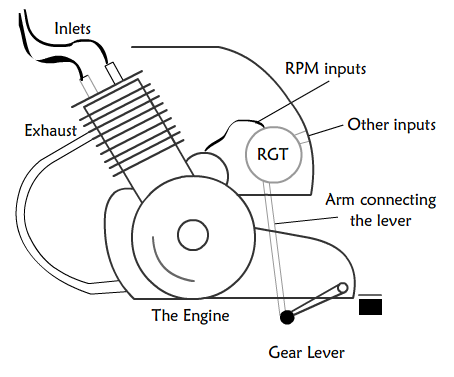
Fig 1
The RGT is placed exactly behind the engine as shown the figure. The arm of the robot is connected to the gear lever of the vehicle. The other output cable from the kit is connected to the clutch. One more cable from the kit is connected to the AAC ( Automatic Acceleration Controller).
The robot is made to take 2 inputs from the vehicle i.e. the speed and the RPM. These inputs are checked every 1/20thof a sec, processed by a high speed micro-controller and signals are sent to the motors that control the gear-shifts, the clutch and a part of accelerator.
AAC:
Automatic AccelerationController is a block of mechanical parts which is placed over the acceleratorcable to control the amount of acceleration externally. The need of AAC comes here when the user is riding the vehicle in Auto-mode and theuser is unaware of when the gear gets shifted. Before the gear is shifted theclutch is held. At this moment the user will still be holding the accelerator which results in increase in the RPM or ‘raise of the engine’. The RGT hence makes use of AAC to avoid this problem by cutting off the connection between the accelerator and the engine.
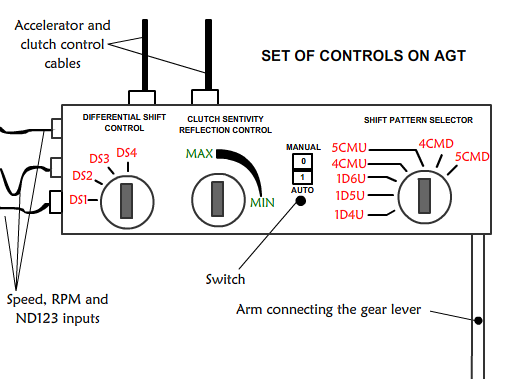
Fig 2.
The robot is also provided withcontrollers for the users to make use of it.
1. P-R-N-D-1-2-3 gear-patternswitches are available on the handle bar of the bike, for the user to control the vehicle when he/she is in Auto-Transmission Mode.
2.Controls attachedto the kit:
a. A switch to turn on and off theRGT.
b. A control knob to control the extentof acceleration:
àThe RGT provides afacility for the user to customize the Differential Shifts.
c. A control knob to change the gearpatterns:
àIn case if the samedevice has to be used on a different vehicle this knob will help in changing the patterns. The most popular patterns can be defined in the kit.
1. 1 down 4 up, 1 down 5 up, 1 down 6 up.
2. 4/5 constant mesh up/down patterns.
d.A control knob for the clutch:
The sensitivity ofthe clutch is different for different vehicles. And also the sensitivity willchange over time with the usage. Hence it becomes necessary to provide a convenient way to reflect the sensitivity changes in the RGT and facilitate smooth transmissions.
Differential Shift:
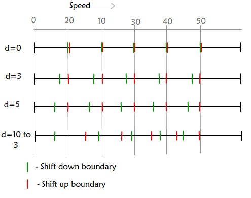
Fig 3.
The differential shift is a concept adopted to avoid the problem of fluctuating speeds. If the microcontroller isprogrammed to shift down the gears in regular intervals of speed same as thatof shift up, the RGT keeps holding the clutch all the time when the speedfluctuates over the gear-shift boundary.
The problem can beovercome by slightly shifting the shift down boundaries left as shown in
Fig. Hence once the gear is shiftedup, for the gear to be shifted down the speed has to come down below the shiftdown boundary which is less than the shift up boundary hence avoiding theproblem of fluctuating speeds.
N D 1 2 3 Pattern:
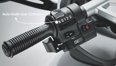
Fig 4.
The above fig. explains how exactlythe controls can be provided for the user and make use of it effectively when he/she is in Auto Mode. N D 1 2 3 gear pattern can be adopted(eliminating R- Reverse and P- Park from standard P R N D 1 2 3 pattern) . The user can select any one of the above when he is in Auto-Mode.
N- Stands for neutral. The gear will be set to neutral as soon as this isselected using the selector switch.
D- Stands for normal drive, shifting the gears at regular speed intervals and similarly shifting down.
1 2 3- The gear is limited to the selected number. Suppose 2 is selected, the gear is not shifted to 3 even when the speed crosses the shift boundary of 2, but the gear might change from 1 to 2 and vice versa. (Used when riding up or down the hill)
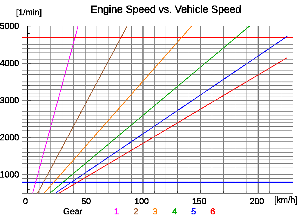
Fig5.
The above graph explains the variation of RPM with speed at different gears. It can be observed that the graph is linear at all gear levels. This is an important criteria on which the microcontroller can be programmed. ‘At a particular gear for a given value of speed the RPM is fixed’. Hence only speed or only RPM can be considered for processing and shifting the gears. (Of course both speed and RPM have to be taken in to account when the vehicle is in 1st gear to ensure smooth movement and set the vehicle into motion from rest!)
X axis: Speed Y axis: RPM
Video Explanation:
The video shows the working of different components of RGT in parallel along with the graph that clearly explains the concept of Shift Boundaries used, and the indicators indicating the current gear,shift pattern and shift type.
The shift pattern shows the patternbeing used currently. The pattern can be any one of the following.
a. 4CMU: 4 speed constant mesh up.
b.4CMD: 4 speed constant mesh down.
c.5CMU: 5 speed constant mesh up.
d.5CMD: 5 speed constant mesh down.
e.1D4U: 1down 4 up.
f.1D5U: 1down 5 up.
g.1D6U: 1down 6 up.
The shift type indicates theacceleration extent which is defined by the variable d. The value of d is the difference between the shift up and shift down boundary. The following codes are displayed in the indicator.
a.DS1 : (Differential Shift 1) . d=3.
b. DS2 : (Differential Shift 2). d=5.
c. DS3 : (Differential Shift 3). d=10to 3. (Refer fig 3.)
Thegraph indicates the variation of speed and rpm at different gears along with the shift up and shift down boundaries. The analog speed and RPM meters display speed and RPM synchronous to the variation in the graph.
The3 D pointer moves over the graph indicating the current value of speed and RPM.
The remaining are the displays of the RGT shifting the gear and the clutch controlat the right time before the shifting is done.
Programming the Controller:
Themicrocontroller is programmed to control 3 different parts. The Arm, the clutch and the accelerator. (All being controlled with the help of a geared high-speedmotor.)
The algorithm followed to program the microcontroller is as shown below.
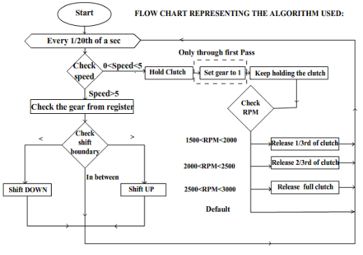
Fig 6.
Themicrocontroller is programmed in such a way that it checks the speed every 1/20thof a second. Once the RGT is turned on it checks the speed( which is initiallyequal to zero). Since the vehicle is at rest the clutch is held and it keeps holding the clutch until it recognizes any changes in the RPM. The RPM raises when the person uses the accelerator which indirectly means that he/she wantsto move the vehicle. Hence the level of RPM is checked and depending on this level the clutch is released.(several levels can be defined for ensuring the smooth movement). As the clutch is released the vehicle gains speed and the control enters into the segment where the gear shift boundary is checked. Before checking the gear shift boundary it is necessary to read the current gear from the register. If the speed is within the shift boundary no action is taken. If it is less, the gear is shifted DOWN, else if it greater the gear is shifted UP.
Use of LabVIEW and NI tools:
The real time processor “CompactRIO”is used to process the real time signals, i.e the speed and rpm. Since CompactRIO is highly efficient in handling the multithreaded processes at amazingly high speeds of 200 to 300MHz, the sudden changes in the signals can be detected, and the changes can be reflected back in the actuators. Superfast signal processing is needed to ensure smooth and quick transmissions. Before the inputs are sent to the processor, Signal Conditioning is performed on the signals and are converted to Digital form. The inputs are taken through the NI9215 modules and the motors are run with the help of NI9505 modules.
Benefits of Using LabVIEW and NItools:
1. Superfast parallel processing is achieved with the help of CRIO processor.
2. Low power consumption by theprocessor.
3. High performance and accuracy of driving the servo motors by the NI9505 modules.
4. Reliable input transfer by Ni9215module.
5. Efficient programming using LabVIEW.
6. Easy and quick interfacing.
OUR TEAM:

Z Brains

SrikanT
ParveZ AND PuneeT
