- Document History
- Subscribe to RSS Feed
- Mark as New
- Mark as Read
- Bookmark
- Subscribe
- Printer Friendly Page
- Report to a Moderator
- Subscribe to RSS Feed
- Mark as New
- Mark as Read
- Bookmark
- Subscribe
- Printer Friendly Page
- Report to a Moderator
Contact Information
University: Universiti Tunku Abdul Rahman
Team Member(s): Chua Kein Huat, Wong Jianhui, Tang Jun Huat, Pang Yap Seng, Lim Khim Yen, Kong Kie Meng
Faculty Advisors: Dr. Lim Yun Seng, Dr. Stella Morris
Email Address: chuakh@utar.edu.my
Project Information
Title: The Future Active Electrical Network Management System
The future active electrical network management system is a system that can be installed in the electrical network integrated with Renewable Energy to provide a full visibility and pervasive control over the loads and supplies in the electrical network.
Products:
NI 9225 3-Ch +/- 300V Voltage Measurement
NI 9227 4-Ch Current Input
Single-board RIO 9632 XT
NI LabVIEW Full Development System 2011
The Challenge:
Nowadays, the highly reliable electrical supply is essential for all the economic activities. Few hours of power outage may cause billion dollars of economic loss and losses of important data. The future electrical networks will be more complex and challenging due to the integration of massive distributed generation. Several technical issues such as the voltage unbalance, voltage rise, energy efficiency and reliability becomes a crucial challenge to the current weak network that is still operated by 50 years old technologies.
The Solution:
The future active network management system is developed to manage energy usage and provide an uninterruptible power supply (UPS) to the electrical network during power outage. Figure 1 shows the experimental setup of the future active network management system. The system comprises of 2 Sunny Island 5048, PV inverter, bus bar, network emulator, load bank, computer, and National Instrument products as listed in the products list. The functions of the equipments are briefly described as follow:
Ø Sunny Island 5048 – a bi-directional power flow inverter connected to 4 batteries that serve as energy storage system to supply power during the power outage. It can be controlled to either inject or absorb power according to the network conditions.
Ø PV inverter – a Photovoltaic inverter that converts sunlight energy into electricity
Ø Bus bar – a point of connection for all equipments and location for current and voltage measurement
Ø Network emulator – a resistive network to represent the resistance of distribution line for different distance
Ø Load bank – a group of resistance controlled by solid state relay to emulate consumer loads
Ø Computer – for managing data and decision making
Ø NI devices – for measurement and control over the whole network
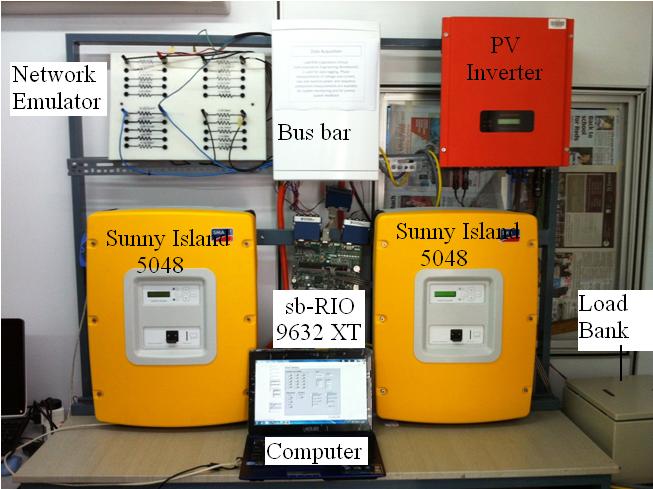
Figure 1: The experimental setup of the future active network management system
Figure 2 shows the electrical diagram of future active network management system. In this project, NI Single-Board RIO 9632XT is chosen because it integrates commercial off-the-shelf hardware to simplify development when designing control, monitoring and test systems. The 110-DIO lines embedded in the board is sufficient for controlling the switching devices in the whole network. The NI 9225 3-Channel Voltage Measurement and NI 9227 4-Channel Current Measurement is connected to the sb-RIO 9632 XT for voltage and current measurement. A user interface is developed in NI LabVIEW full development system 2011. NI LabVIEW can be easily integrated with NI devices for measurement and control which solve many problems in integration of hardware and software as well as the needs of code composer. In fact, NI provides a full package of solution over the whole process from design, simulation to implementation. Furthermore, programming is no longer a nightmare for programmers because NI LabVIEW provides a powerful and yet user friendly graphical programming tool. NI LabVIEW also provides a very important debugging tool and error cluster to identify problems in block diagram.
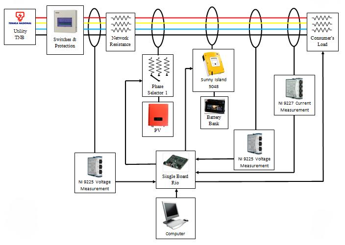
Figure 2: The electrical diagram of future active network management system
Hardware description
Figure 3 shows the distribution line model to emulate the line resistance of the distribution network. It consists of four set of resistors that can be connected to the three phase-four wire system. The resistance for each phase can be varied from 0.11 Ohm to 0.33 Ohm which represents the distance of 200 m up to 600 m respectively.
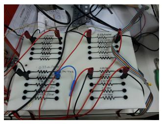
Figure 3: The transmission line model
The photovoltaic (PV) system shown in Figure 4 consists of inverter and battery bank. The battery bank emulates a PV panel to provide a power up to 1500 W. The reason of using battery bank instead of PV panels is that the PV power output is more consistent and independence from change of weather. Hence, it is more suitable for laboratory testing. The DC power is converted into AC power via the PV inverter and connected to the three phase distribution network via phase selector. A phase selector is used to connect the PV inverter to the phase that has lowest voltage. This can help to reduce the voltage rise on the phase and at the same time reduce the voltage unbalance of the network. The phase selector is controlled by solid state relay which is connected to the integrated digital I/O in the sb-RIO 9632 XT.
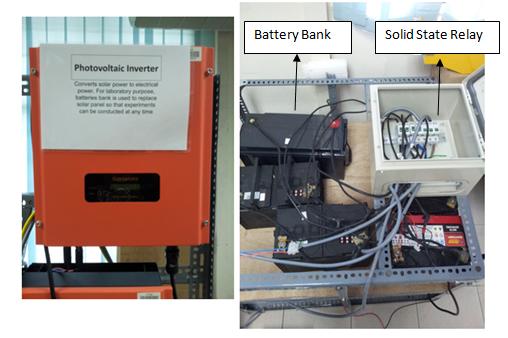
Figure 4: PV system
A load bank shown in Figure 5 consists of group of resistors and solid state relay. The load in each phase can be varied from 0 W to 1000 W in step of 200 W. The load bank serves the function to emulate the consumer load consumption. To ease the understanding of loading condition in the three phase network, the loading condition in the load bank is represented in matrix form as [A B C], where A, B and C are the load values for each phase. For example, [1000 0 0] represents the load at phase A is 1000 W where the load at phase B and phase C are zero.
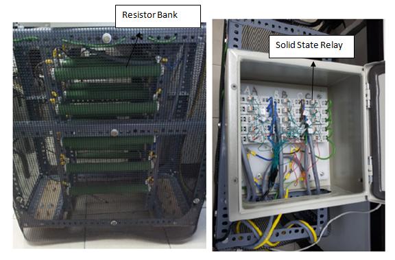
Figure 5: Load bank
Figure 6 shows a Sunny Island 5048, a bi-directional power flow inverter. This device is able to provide power supply during the power outage to ensure a continuous power supply to the network. It consists of 4 batteries that offer an energy storage up to 5760 Wh. It can be controlled to either inject or absorb power according to the network conditions. The batteries are monitored diligently and utilized optimally.

Figure 6: Sunny Island 5048
Software description:
The future active network management system is developed in NI LabVIEW 2011. The graphical user interface is as shown in Figure 7. The basic parameter tab consists of a load bank control, phase selector control, Sunny Island control, measurement of power, energy, current, voltage, voltage unbalance factor (VUF), power losses, and indicator lights. Figure 8 shows the block diagram of the LabVIEW vi.
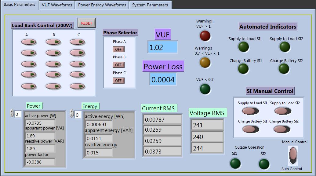
Figure 7: The graphical user interface for the future active network management system
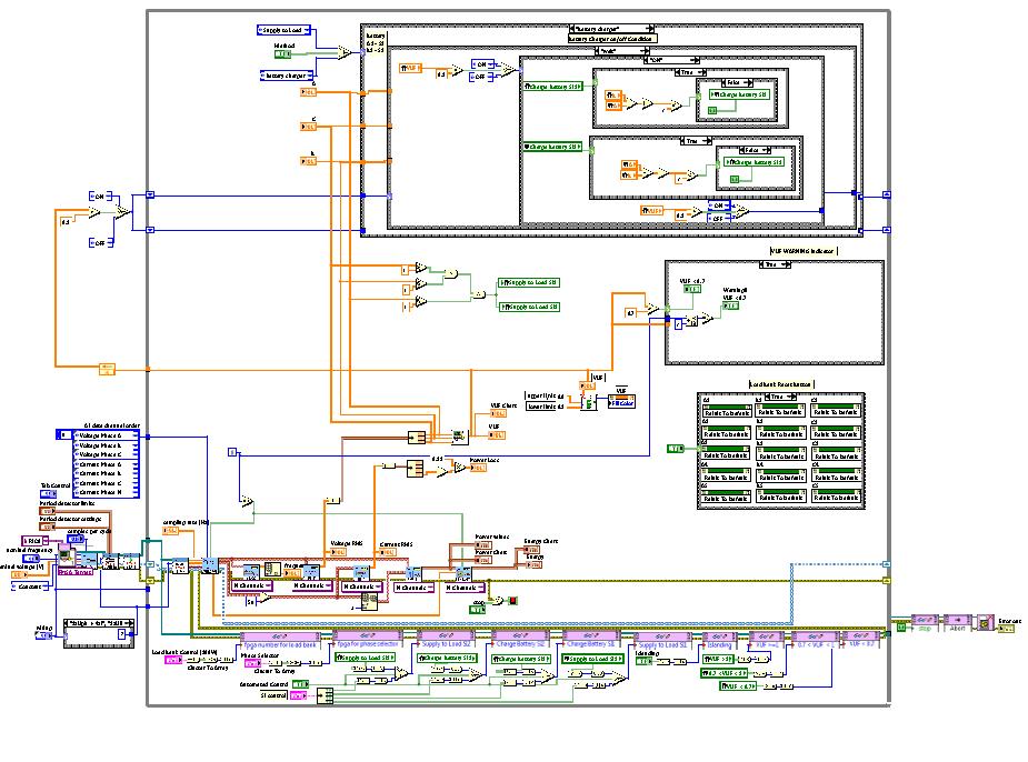
Figure 8: Block diagram of the LabVIEW vi
There are 3 indicator lights to indicate the voltage unbalance factor (VUF) level. The indicators will blink when the VUF exceed 1 %. There are two method of controlling the Sunny Island 5048, namely the manual control and auto control. When the manual mode is selected, the Sunny Island is controlled by the “SI Manual Control” to either supply power to load or absorb power to charge batteries. When the auto control is selected, the Sunny Island will be connected to the network based on the control algorithm. The “Automated indicators” shows the connection of Sunny Island for different scenario. The active power, reactive power, apparent power and power factor of the network can be monitored and recorded. These parameters provide a clear view on the power flow direction and the quality of the power supply. Typically the power factor should not be lower than 0.85, or remedial action need to be taken in order to improve the power factor of the network.
The voltage unbalance factor (VUF) is calculated from the network three phase voltage. According to the Malaysia Grid Code, the voltage unbalance factor shall not exceed 1 % for five occasions within any thirty minutes time period at the terminals of a user’s installation. Inherently, the VUF of the network is around 0.2 % to 0.4 %. The control of the future active network management system can be divided into 2 parts:
Part 1: Voltage Unbalance Mitigation
The system is designed to react such a way to avoid the network VUF from exceeding 1 %. The system will react when the VUF reach 0.8 %. If the VUF is greater than 0.8 %, the system will start the compare the voltage at each phase. Several case studies are conducted to represent the different scenarios faced by actual network.
The first case study is that the network is connected to a PV inverter with output power of 1000 W. The voltage of the three-phase network are measured and compared. The load profile of the network is [1000 0 0], which means that phase A is loaded with 1000 W of load while phase B and phase C is in no-load condition. This results in phase A having lowest voltage among the three phases, and causes the VUF rise to 2 %. The system will channel the PV inverter to phase A via the phase selector. This has successfully mitigated the VUF to 0.4 % because the load is directly supplied by the PV inverter and hence the load profile becomes [0 0 0], a balance load. When the demand of power decreased in phase A, say [0 0 0], the PV inverter cause the VUF to rise to 2 % because the load profile is [-1000 0 0]. In this case, the Sunny Island will be connected to the PV inverter to store the excess power into battery to maintain the balance of all three phases. As a result, the load profile will become [0 0 0] and the VUF of the network will be minimized.
The second case study is that when the PV inverter does not output any power and the network has the load profile of [0 1000 1000], which means that the phase A is no-load condition while phase B and phase C are connected to 1000 W of load. In this case, the VUF is at around 3 % in the network. In order to make the load to be balance at all phases, the Sunny Island will take 1000 W from phase A and store it into the battery. Hence, the load profile becomes [1000 1000 1000] and the voltage unbalance has been mitigated to 0.35%.
In the third case study, the PV inverter is not connected to the network and the load profile of the network is [1000 0 0]. The VUF at this moment is 2 %. The Sunny Island will be connected to the phase A and supply 1000 W to the load. Again, the load profile becomes [0 0 0] and the VUF has been mitigated to 0.35 %.
Part 2: Power outage operation
The future active network management system ensures the continuity power supply to consumers during the power outage. In this system, there are only two units of Sunny Island 5048 connected to phase A and phase B respectively. In order to provide power supply to all the three phases, three units of Sunny Island is required. However, due to the limitation of budget, there are only two units of Sunny Island available at the moment. During the power outage, the Sunny Island will immediately take over the grid to continue supply to the network. Since there are only two phases connected to Sunny Island, hence any load connected to phase C will not receive any power during outage. Nevertheless, this problem can be solved by installing another unit of Sunny Island on the phase C.
Conclusion
The future active network management system is capable of improve the reliability of the network by providing an Uninterruptible Power Supply (UPS). This is important to support the economic activities especially nowadays most of the trading is done via internet. Confronting the massive integration of Renewable Energy into the electrical network, the future active network management system is capable of managing energy such a way to meet the technical requirements as well as improving the efficiency of the network.
