- Document History
- Subscribe to RSS Feed
- Mark as New
- Mark as Read
- Bookmark
- Subscribe
- Printer Friendly Page
- Report to a Moderator
- Subscribe to RSS Feed
- Mark as New
- Mark as Read
- Bookmark
- Subscribe
- Printer Friendly Page
- Report to a Moderator
Contact Information
University: University of Southampton
Team Members (with year of graduation):
David Aggus (2015)
Noorvir Aulakh (2015)
Iordanis Karapanagiotis (2015)
Robert Knight (2015)
Alden Laslett (2015)
Hawkar Mahmod (2015)
Michalis Rodosthenous (2015)
Project Supervisors: Dr Dina Laila, Ms. Beejal Shah
Email Address: nsa2g11@soton.ac.uk
Project Information
Title: Autonomous Quadrotor Design and Build Using National Instruments myRIO
Description: This project deals with the design of an autonomous quadcopter capabale of navigating a cluttered environment with all systems built from scratch including the flight controller and the navigation system.
Products: NI myRIO, NI LabVIEW 2014 Student Edition, LabVIEW Vision Development Module, NI LabVIEW MathScript RT Module, NI LabVIEW Control Design and Simulation Module, LabVIEW Robotics Module, MATLAB
The Challenge: To design a control system from scratch that would taken commands from the vision and navigation system and guide the quadrotor in the appropriate direction in addition to ensuring basic flight stability.
The Solution:
In this project, we present the design of an autonomous quadrotor using the National Instruments (NI) myRIO architecture. Given its integration of high level and low level tasks, we decided to use the myRIO towards attaining the otherwise complex task of building a flight controller for the inherently unstable quadrotor system. Quadrotors have become increasingly popular in both hobbyists and professional circles over the last few years. This popularity is owed primarily to their relative versatility, simplicity and low-cost. To expand on the basic capabilities however, it is important to understand the basic principles of flight dynamics and control. Most commercial quadrotors come preconfigured with an autopilot and remote control system. In our approach we developed the flight controller starting from scratch, which presented us the ideal opportunity to delve deeper into the working principles of instrumentation, control and sensor fusion. It also accorded us the chance to build onto our understanding of low level electronics and microcontroller functioning. The project was split into a number of sub-tasks addressing the hardware, software and testing sections. The aim was to concurrently develop the instrumentation and hardware, autopilot and flight controller, vision and navigation system, and the testing equipment, with a view of achieving confluence towards the end of the project. We also decided to focus on using LabVIEW throughout the build in order to promote consistency and code portability.
We started our build using the most basic and essential components of the system. A simulation of the system was implemented in LabVIEW based on the mathematical model derived earlier from first principles. This served as a testbed for examining the dynamic stability of the system in response to a variety of input conditions. It allowed us to “virtually” tune the PID controller gains and form a basis for their estimation in the practical implementation. To complete the state estimation, data from the GPS was acquired for global positioning along with range information from an ultrasound sensor and data from a barometer to give altitude measurement. We designed and manufactured a 3-DoF rig for testing the quadrotor and performed FEA to ensure structural robustness. This system was designed to take flight commands from the vision and navigation system. We implemented object avoidance, mapping and object detection in LabVIEW using integrated MATLAB code.
The project was completed over 5 months and is currently in beta stage of development. We attained successful flight stability and control along with object detection and avoidance as well as basic mapping of the environment. The next step in the project will be carried out next year which focus on integrating the basic systems already developing and achieving full autonomy.
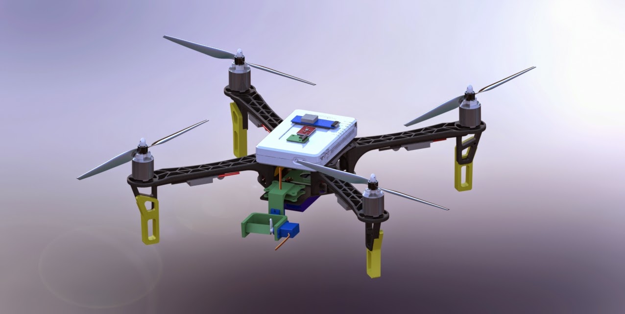
Fig 1. Final Quadrotor model created using SolidWorks CAD software.
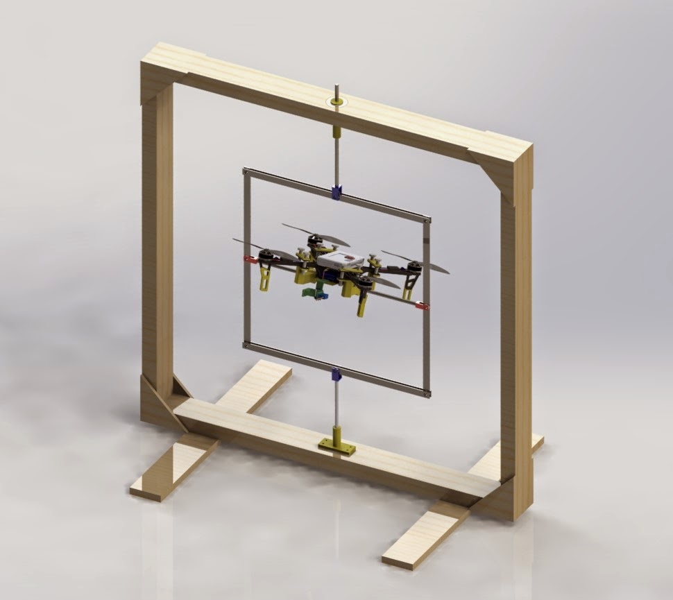
Fig 2. Computer rendered quadrotor in attitude testing test rig.
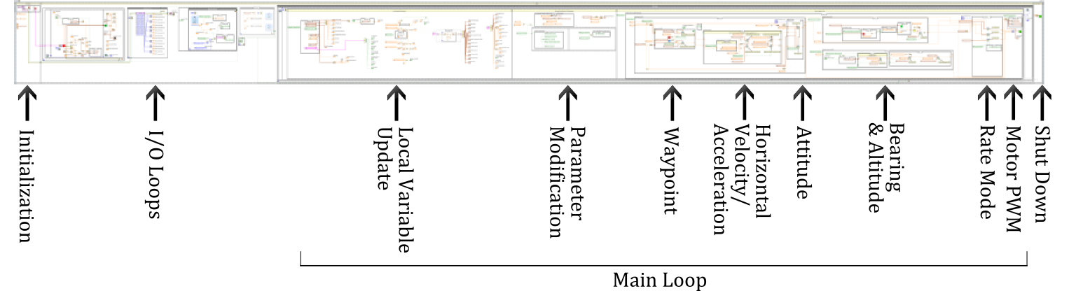
Fig 3. Ground up autopilot/flight controller VI.
Attach Poster
(See attached)
- Mark as Read
- Mark as New
- Bookmark
- Permalink
- Report to a Moderator
Hi,Noorvir,
Which sensor modules are required, please tell me their models.
Thank you.
