- Document History
- Subscribe to RSS Feed
- Mark as New
- Mark as Read
- Bookmark
- Subscribe
- Printer Friendly Page
- Report to a Moderator
- Subscribe to RSS Feed
- Mark as New
- Mark as Read
- Bookmark
- Subscribe
- Printer Friendly Page
- Report to a Moderator
Description:
This document shows three ways to controls LEDs:
1. A low current LED (2mA)
2. A typical LED (20mA)
3. A RGB LED
Please Note:
The problem to run LEDs with a myRIO is that the digital output can only supply 4mA. A typical LED on the other side needs about 20mA. Therefore you can´t control a LED with digital outputs alone. The examples bellow will show you some solutions.
Furthermore it is important to note that all the digital outputs/inputs of Connector A and B have a pull-up resistor and the logic level after initialization is high (1). The LEDs will glow if the VI doesn´t run. If a logical level of low (0) is preferred the digital outputs of Connector C could be used.
1. Low current LED
What is a low current LED?
A normal LED don´t glow if the current drops under 8 to 10 mA. Low Current LEDs have the ability to glow already with 5 mcd at 2 mA. If you increase the current the LED is glowing brighter. At 20mA the maximum illuminating power is reached.
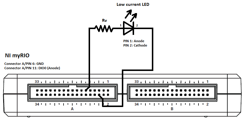
Example with L-53LGD
Information from Datasheets:
Forward voltage off LED: 2.2 V
Output voltage myRIO: 3.3 V
Output current myRIO: max. 4 mA
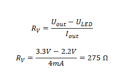
--> In practice take the next larger one: Rv= 330 Ω
2. Typical LED (20mA)
A typical LED needs a current of 20 mA to get its maximum illuminating power. The Digital Output can only supply 4 mA. Therefore we need a NPN transistor to connect our LED to the +5V power Output which can supply up to 100 mA.
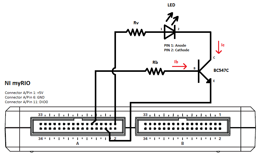
Example with L53 HD and BC547C:
Information from Datasheets:
Forward voltage off LED: 2.25 V
Output voltage myRIO: 5 V
Output current myRIO: max. 100 mA
Voltage DIO myRIO: 3.3 V
Transistor hFE: 400
What is hFE?
hFE or β of a transistor is the current gain or amplification factor of a transistor. Which means by how much the base current is amplified.
Determination of Rb:
We want to calculate the maximum of the basis resistor (Rb) to switch off and on up to 5 LEDs. In practice we only use half the value of hFE to make sure that the transistor is in the „Saturation Region”.
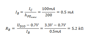
--> In practice take the next lower one: Rb= 4.7 kΩ
Determination of Rv:
Rv is depending on how many LEDs you want to run. If you want to run more than one, the others must be parallel to the first one.
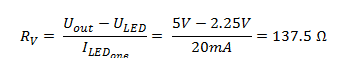
--> In practice take the next larger one: Rv = 150 Ω
3. RGB LED
A RGB LED can mix the colors Red, Green and Blue to every possible color. The connection diagram is more complicated because RGBs LEDs have only two Ground Pins but four Input Pins. To be able to control every LED alone, the connection diagram below is needed.
Unfortunately the green LEDs are currently not as efficient as the red or the blue ones. Therefore mixing the colors is not always perfect. (You don´t get a perfect white)
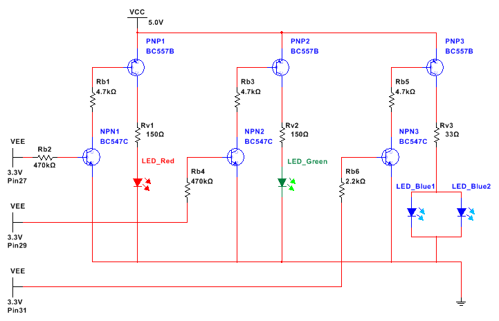
The simulation is made in Multisim 13.0 and is attached bellow.
Example with LF5WAEMBGMBC, BC547C and BC 557B:
Information from Datasheets:
Forward voltage off LED Red (E): 2.0 V
Forward voltage off LED Green (G): 2.2 V
Forward voltage off LED Blue (MB): 3.8 V
Output voltage myRIO: 5 V
Output current myRIO: max. 100 mA
Voltage DIO myRIO: 3.3 V
Transistor NPN hFE: 400
Transistor PNP hFE: 200
Determination of Rb1, Rb3, Rb5:
We want to calculate the maximum of Rb to be able to have a current of 100 mA.
In practice we only use half the value of hFE to make sure that the transistor is in the „Saturation Region”.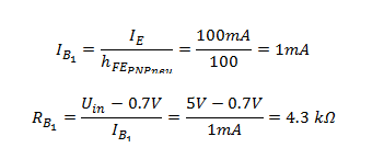
--> In practice take the nearest/lower one: Rb1 = Rb3 = Rb5 = 4.7 kΩ
Determination of Rb2, Rb4, Rb6:
We want to calculate the maximum of Rb to be able to have a current of 1 mA.
In practice we only use half the value of hFE to make sure that the transistor is in the „Saturation Region”.
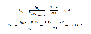
--> In practice take the next lower one: Rb2 = Rb4 = Rb6 = 470 kΩ
Determination of Rv1, Rv2, Rv3:
Rv determines how much current is flowing through the LEDs. In this example 20mA is needed for each LED. That means that through Rv3 (blue) 40mA are necessary.
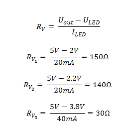
--> In practice take the next larger one: Rv1 (rot) = 150 Ω Rv2 (grün) = 150 Ω Rv3 (blau) = 33 Ω
