- Document History
- Subscribe to RSS Feed
- Mark as New
- Mark as Read
- Bookmark
- Subscribe
- Printer Friendly Page
- Report to a Moderator
- Subscribe to RSS Feed
- Mark as New
- Mark as Read
- Bookmark
- Subscribe
- Printer Friendly Page
- Report to a Moderator
Title:
Digilent Motor Adapter for myRIO Stepper Motor Example Code
Description:
Digilent has a motor adapter specifically designed for myRIO. The motor adapter allows you to easily connect and control either one stepper motor, two DC motors, or two servos independently through the MXP connector on your myRIO. No additional circuitry is required.
Overview of Stepper Motors:
A stepper motor is a brushless DC electric motor. In order to rotate a full rotation, the motor must go through a certain number of equal steps. The motors position is not tracked, but the motor can be commanded to hold its position. The benefit to a stepper motor is the ability to control torque, speed, and having the ability to hold its position at any given step. For further information on stepper motors look at the link below.
https://en.wikipedia.org/wiki/Stepper_motor
Steps:
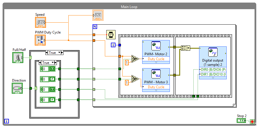
A full step is when you change direction of the coils in the sequence listed below. A half step follows the same sequence as the full step, but includes turning the PWM on and off. In steps 2, 4, 6, and 8 the PWM is turned off before the direction changes, while in steps 1, 3, 5, 7 the direction must change before the PWM is turned on. In order for this process to preform correctly a flat sequence structure is required. The for loops inside the flat sequence structure are used to determine if the PWM should be turned on or off. You can reverse the direction of the motor by reversing the sequence. With this code you have control over the strength of the motor, direction, speed, and the option between full and half steps.
Full Step:
1 | 2 | 3 | 4 | |
Motor 1 | T | F | T | F |
Motor 2 | T | T | F | F |
Full Step Reversed:
1 | 2 | 3 | 4 | |
Motor 1 | T | F | F | T |
Motor 2 | T | F | T | F |
Half Step:
1 | 2 | 3 | 4 | 5 | 6 | 7 | 8 | |
Motor 1 | T | 0 | F | F | F | 0 | T | T |
Motor 2 | T | T | T | 0 | F | F | F | 0 |
Half Step Reversed:
1 | 2 | 3 | 4 | 5 | 6 | 7 | 8 | |
Motor 1 | T | T | 0 | F | F | F | 0 | T |
Motor 2 | 0 | F | F | F | 0 | T | T | T |
T = True F = False 0 = Off
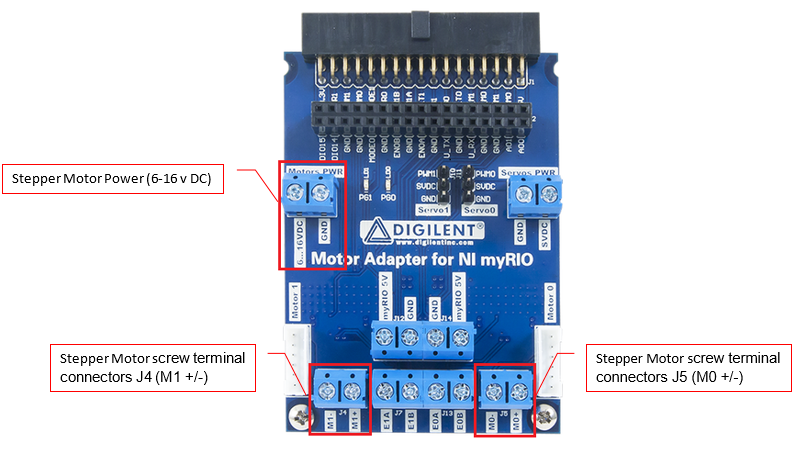
Connecting the Stepper Motor:
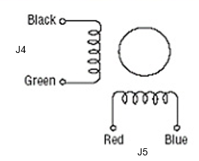
A stepper motor can be connected to the motor adapter through screw terminals J4 and J5. It is important that the wires are attached in the correct order. Make sure that J4 has the two wires from the first coil, and J5 has the two wires from the second coil. Consult the data sheet for the stepper motor if you are not sure which wires go together. The terminals connect to the proper pins on the MXP port on the myRIO, so you can use the express VIs listed below.
- The PWM express VI can be used to change the torque of the motor. (PWM 0 and PWM 1)
- The Digital Output express VI can be used to change the direction of each coil. (Pins 23 and 31)
Attach Code
- Mark as Read
- Mark as New
- Bookmark
- Permalink
- Report to a Moderator
what is the maximum speed i can give in this program?
