Description:
Simple FPGA personality that implements dedicated DIO lines
Instructions on how to use Code:
Modified Pin-out:
OnBoard DIO (Input and Output already implemented on the myRIO)
Output:
- DO.LED3:0 is written onto LED0, LED1, LED2, and LED3 (the 4 LEDs on the myRIO)
Input:
- Button0 (on the myRIO) is read from and put on DI.BTN
Outward Facing DIO
Output:
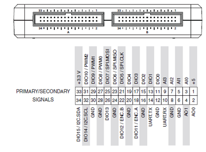
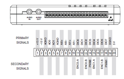
- -DIO.B15:0.OUT is split into upper and lower half and written onto the ConnectorB/DIO15:8 and ConnectorB/DIO7:0 pins respectively
- DIO.C_7:0.OUT is written onto the ConnectorC/DIO7:0 pins
Input:
- ConnectorA/DIO15:8 and ConnectorA/DIO7:0 pins are read from, joined, and put on DIO.A_15:0.IN
< If your code is a new FPGA Personality, please add changed pin-outs in either an Excel spreadsheet or by modifying the pictures below>
< Please delete pin-out pictures if not relevant to your code>
Code: AllDIO.zip
Sunaina K.
Product Marketing Manager for CompactRIO & TSN
Making the intangible, tangible
