- Document History
- Subscribe to RSS Feed
- Mark as New
- Mark as Read
- Bookmark
- Subscribe
- Printer Friendly Page
- Report to a Moderator
- Subscribe to RSS Feed
- Mark as New
- Mark as Read
- Bookmark
- Subscribe
- Printer Friendly Page
- Report to a Moderator
6x6 MIMO-OFDM System with NI USRP RIO
The 6x6 MIMO-OFDM system has been implemented with NI USRP RIO hardware in both LabVIEW 2015 as well as LabVIEW Communications 2.0. The material below is relevant to both of these versions but in order to get these two versions running you need to have LabVIEW 2015 and LabVIEW Communications 2.0 (respectively) installed. For more background on this system, refer to the original 6x6 MIMO-OFDM System section of this document.
Overview:
This part of the document describes how to implement the 6x6 MIMO-OFDM System from the previous section with NI USRP RIO hardware. This system uses the same channel training sequences as the previous version and it can still support 2x2 MIMO and 4x4 MIMO with proper configuration.
NI USRP RIO devices have two daughterboards, so that each device can support 2 RF channels. Ultimately, this feature allows us to implement a 6x6 MIMO System with 6 USRP RIO devices.
Hardware Configuration:
The following hardware was used to implement this system:
- One PC
- PCI Express Switch Box
- 6 USRP RIO devices (NI USRP 2950R and NI USRP 2942R devices were used)
- 12 antennas
- 1 octoclock (with 10MHz reference clock and PPS output)
- PCIe x4 cables
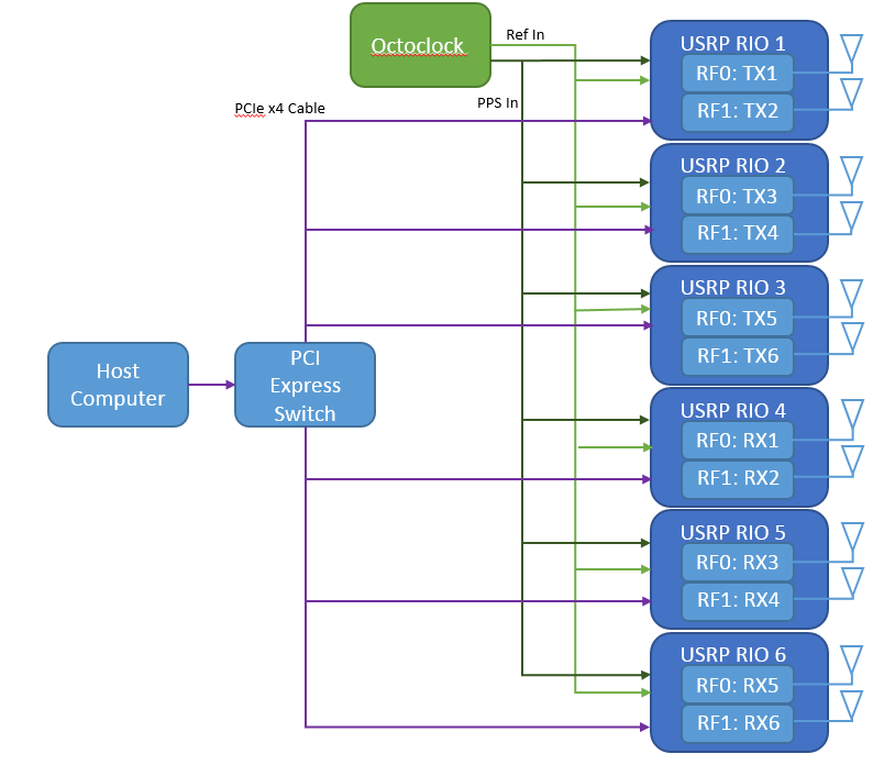 Figure 1: The 6x6 MIMO System Hardware Setup Diagram
- Connect one antenna to each RF port on each of the 6 USRP RIO devices (NI recommends using RX1/TX1 port for simplicity). For desired operation, the transmitting antennas should be at least half a wavelength (of the carrier frequency used) apart.
- Connect each USRP RIO device to the octoclock to receive the Ref In and PPS In Signal
- Connect each USRP RIO device to the PCI Express Switch Box via PCIe x4 cables
- Connect the switch box to the host computer
- Power up all 6 USRPs and the external clock to complete the hardware configuration procedure.
Software Configuration:
The usrp_mimo_tx.vi and usrp_mimo_rx.vi function exactly the same as the previous version. However, these VI’s have been designed to support both RF channels on the USRP RIO devices. In the previous version of this MIMO system, each device was only configured to support one RF channel. Since yhis software enables both channels on the USRP RIOs, entering two devices into the Device IP Array would enable four channels, so you would need to configure Clock Source, Frequency Source, Active Antennas, and Channel Gains for four channels.
*Original 6x6 MIMO-OFDM System*
Overview
This document describes how to set up a 6x6 multiple input, multiple output (MIMO) system using NI LabVIEW software and NI USRP™ (Universal Software Radio Peripheral) hardware. After a brief discussion of MIMO, the paper examines the hardware and software based on LabVIEW for a 6x6 MIMO-OFDM system using 4-QAM as modulation scheme. The system presented here is also capable of working as a 2x2 MIMO and 4x4 MIMO system with appropriate parameter configuration.
Table of Contents
1. What Is MIMO?
2. Implementing a 6x6 MIMO System
3. 6x6 MIMO System: Hardware Configuration
4. 6x6 MIMO System: Software Configuration
5. Working With the Example
6. Building a 6x6 MIMO System in LabVIEW
i. Preparing a Signal for Transmission
ii. Signal Recovery
7. Results
8. Additional Resources
What is MIMO
With MIMO, you can increase wireless system performance without increasing power consumption. It is based on the idea that when using multiple antennas, the transmitted signal progresses through different wireless channels, from the transmitter antennas to the receive antennas, to create a capacity gain by exploiting channel diversity.
To learn more about MIMO,
- J. W. Massey, J. Starr, Seogoo Lee, Dongwook Lee, A. Gerstlauer, and R. W. Heath Jr. Implementation of a real-time wireless interference alignment network. To appear in the Proc. of the Asilomar Conference on Signals, Systems and Computers, 2012.
*Please cite this paper if you want to build on this code and publish something with it.
Implementing a 6x6 MIMO System
The MIMO system described here uses Orthogonal Frequency Division Multiplexing (OFDM) and 4-QAM as modulation scheme. Channel training sequence and synchronization training sequence are added at the transmitter to facilitate the receiver operation. Using these training sequences impact of different channel impairments such as time delay, carrier frequency offset, multipaths, and residual channel perturbation are estimated and corrected at the receiver.
6x6 MIMO System: Hardware Configuration
You need twelve NI USRP transceivers for a 6x6 system because individual transceivers are not capable of two simultaneous transmits or receives. The following configuration is recommended:
- One PC with a free Gigabit Ethernet port.
- Gigabit Ethernet switch
- 12 USRPs (NI USRP-292X recommended)
- 12 antennas
- 2 external clocks
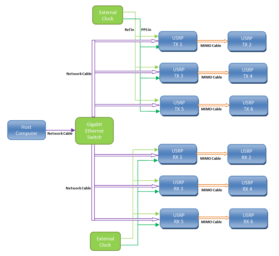
Figure 1: The 4x4 MIMO System Hardware Setup Diagram
Figure 1 shows the configuration you can use for this 4x4 MIMO system. The detailed configuration procedure to set up the transmitter side is given here (the receiver configuration follows the same procedure):
- Connect one antenna to each of the 6 USRPs that are going to serve as the transmitter (NI recommends using RX1/TX1 port for simplicity). For desired operation, the transmitting antennas should be at least half a wavelength (of the carrier frequency used) apart.
- Out of the 6 USRPs that are going o serve as the transmitter, connect any three of them (USRP TX2, USRP TX3, and USRP TX5) directly to the Gigabit Ethernet Switch with appropriate gigabit Ethernet cable.
- Connect USRP TX2, USRP TX3, and USRP TX5 to the external clock to receive the reference signal and the PPS signal.
- Connect USRP TX1 to USRP TX2, USRP TX3 to USRP TX4, and USRP TX5 to USRP TX6 via MIMO cables.
- Power up all 6 USRPs and the external clock to complete the hardware configuration procedure.
Please repeat the same steps on the receiving side of your system.
6x6 MIMO System: Software Configuration
This 6x6 MIMO example is a LabVIEW application that requires the following software components:
- NI LabVIEW Version 2011 (or later) system design software—Full, Professional, or Student Edition
- NI-USRP Version 1.1
- NI LabVIEW Modulation Toolkit Version 4.3.1
- 6x6 MIMO Example VIs
Working with the Example
Unzip the associated zip file to a new folder and open the file entitled usrp_mimo_tx.vi and usrp_mimo_rx.vi in LabVIEW. Make sure that the location of the folders that contain the MathScript files are included in the MathScript Search Path list. The process of including the folder location in the search path list is given bellow:
- Open LabVIEW
- Select Tool>Options
- Under the Category list, select MathScript
- On the "Search Path" panel include all the folder locations that contains the MathScript files used in this example.
- The front panel of the usrp_mimo_tx.vi (Figure 2) contains the parameters for the NI USRP transceivers that are used for the transmitter. Set the controls of these parameters with the following guidelines in mind:
Device on Array: You can select different MIMO configuration by selecting appropriate number of devices in the transmitter. For 6x6 MIMO system, make sure all the 6 buttons are selected.
Device IP Array: Enter the IP addresses associated with the NI USRP TX1, TX2, TX3, TX4, TX5, and TX6.
Clock Source: Select PpsIn for USRP TX2, TX3, and TX5 and MIMO for USRP TX1, TX4, and TX6.
Frequency Source: Select RefIn for USRP TX2, TX3, and TX5 and MIMO for USRP TX1, TX4, and TX6.
Active Antennas: Enter the appropriate antenna ports TX1 or TX2 that you connected the antennas to each of the devices. For the transmitter in the example, we connected all the antennas to the TX1 port of the devices.
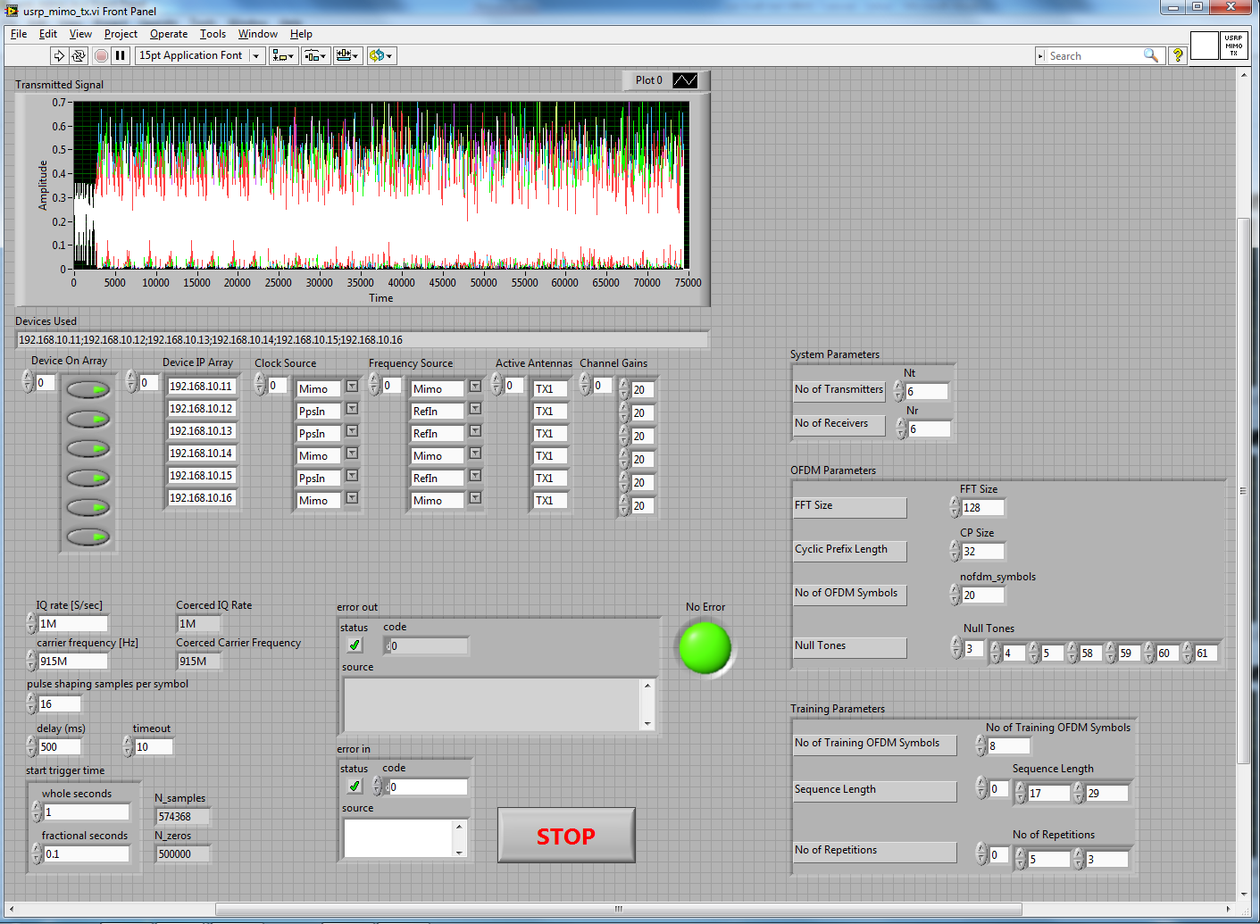
Figure 2: Front panel of the usrp_mimo_tx.vi
I/Q rate [S/sec], carrier frequency [Hz], and pulse shaping samples per symbol: For the I/Q rate, carrier frequency, and pulse shaping samples per symbol enter the sample rate, carrier frequency, and the samples per symbol. These parameter values have to be the same for both the transmitter and receiver.
delays (ms), and timeout: delays specifies the time in milliseconds that specifies the time between two consecutive transmissions of the data samples. timeout specifies the time to wait in seconds, before returning an error if the requested number of samples have not been generated. A negative value indicates to the driver to wait indefinitely.
start trigger time: Configures the start trigger generated by the onboard device timer and specifies the time to start the trigger. In case of multiple synchronized devices, all of them must use a Start Trigger.
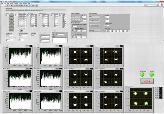
Figure 3: Front panel of the usrp_mimo_rx.vi
- The front panel of the usrp_mimo_rx.vi (Figure 3) contains the parameters for the NI USRP transceivers that are used for the receiver. Set the controls of these parameters with the following guidelines in mind:
Device on Array: You can select different MIMO configuration by selecting appropriate number of devices in the receiver. For 6x6 MIMO system, make sure all the 6 buttons are selected.
Device IP Array: Enter the IP addresses associated with the NI USRP RX1, RX2, RX3, RX4, RX5, and RX6.
Clock Source: Select PpsIn for USRP RX2, RX3, and RX6 and MIMO for USRP RX1, RX4, and RX5.
Frequency Source: Select RefIn for USRP RX2, RX3, and RX6 and MIMO for USRP RX1, RX4, and RX5.
Active Antennas: Enter the appropriate antenna ports RX1 or RX2 that you connected the antennas to each of the devices. For the transmitter in the example, we connected the antennas to the RX1 port of the first five devices and to the RX2 port of the last device.
I/Q rate [S/sec], carrier frequency [Hz], and N_MF: For the I/Q rate, carrier frequency, and N_MF enter the sample rate, carrier frequency, and the samples per symbol for he matched filter. These parameter values have to be the same for both the transmitter and receiver.
Num samps per fetch, and trigger level: Num samps per fetch specifies the number of samples the receiver grabs per processing cycle. trigger level specifies the threshold to which the receiver compares the received signal strength to detect the presence of the transmitted signal.
start trigger time: Configures the start trigger generated by the onboard device timer and specifies the time to start the trigger. In case of multiple synchronized devices, all of them must use a Start Trigger.
- The front panel of the usrp_mimo_tx.vi (Figure 2) and usrp_mimo_rx.vi (Figure 3) also contain the system parameters that are same for both the transmitter and receiver. Set the controls of these parameters with the following guidelines in mind:
System Parameters: System parameters include Number of Transmitting Antennas and Number of Receiving Antennas. For this example both the parameter values are selected to be six (6).
Training Parameters: Number of Training OFDM Symbols specifies the OFDM symbols that are used for training purpose. Sequence Length specifies the length of the training sequence and No of Repetition specifies the repetitions of this training sequence.
OFDM Parameters: OFDM parameters include the FFT Size, Cyclic Prefix Length, No of OFDM Symbols, and Null Tones. Null Tones specifies positions of the null tones in the frequency domain. For this example the positions of the null tones used are: [1:5, 58:63, 64:69, and 123:128] (in this example the fft size used is 128).
With the parameters set appropriately, you can run both the VIs. Doing so; the usrp_mimo_tx.vi starts to continuously transmit modulated signal. The usrp_mimo_rx.vi upon receiving the signal performs different signal processing and the received signal stream and the detected constellation diagrams of all the 6 receiving antennas are displayed in the usrp_mimo_rx.vi.
Building an 6x6 MIMO System in LabVIEW
This section describes the key components of the 6x6 MIMO system:
i. Preparing the Signal for Transmission:
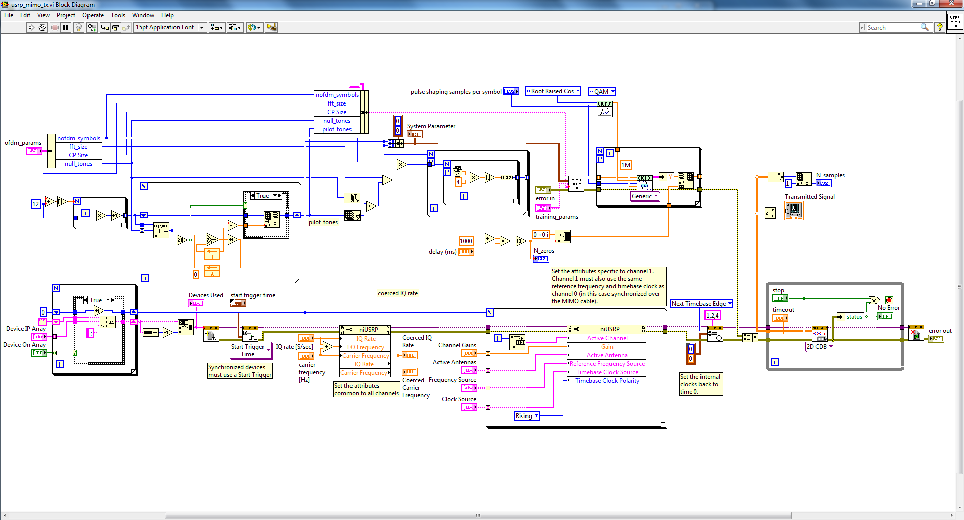
Figure 4: Block diagram of the usrp_mimo_tx.vi
Figure 4 presents the block diagram of the usrp_mimo_tx.vi. As can be seen from the block diagram, it calculates the pilot tones based on the OFDM Parameters. Pilot tones are spread over the frequency range. In this example, we have added one pilot tone after every twelve data tone. The positions of null tones also have to be considered while adding pilot tones. Then the VI calculates the data length (FFT size – length of pilot tones – length of null tones) and generates required number of data bits. These generated bits along with all the parameters from the front panel and the calculated pilot tone positions are fed into the mimo_ofdm_tx.vi to get the QAM modulated OFDM signal with training and synchronization sequence for all the six transmitting antennas. The TX VI also makes sure all the devices in the transmitter are properly configured for the transmission operation. The mimo_ofdm_tx.vi prepares the signal for transmission and the block diagram (Figure 5) of the VI shows that the signal processing is done using MathScript Node in LabVIEW.
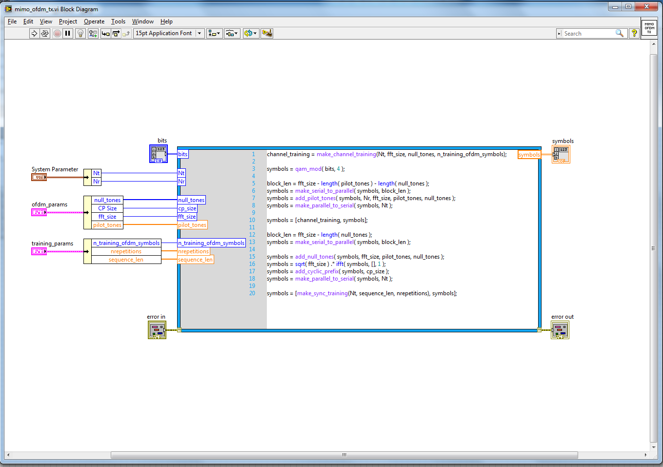
Figure 5: Block diagram of the mimo_ofdm_tx.vi
ii. Signal Recovery:
As can be seen from the block diagram of mod_classifier_RX.vi (Figure 6 and Figure 7), the RX VI first calculates the pilot tone positions from the OFDM parameters as was done in the transmitter. It also sets up all the USRPs at the receiver to have the appropriate operating configurations. In order to fetch a particular number of samples for each processing cycle, the RX VI then calls the usrp_rxrf_trigger_and_capture.vi subVI.
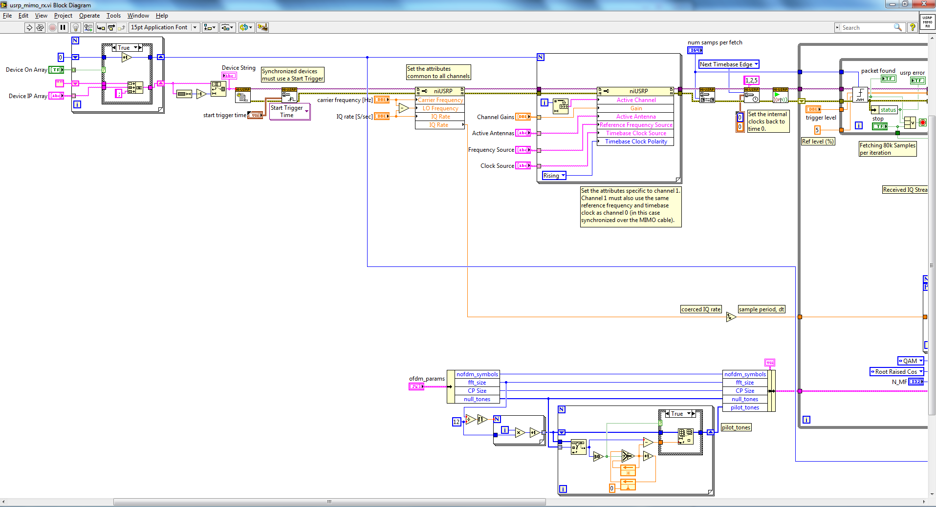
Figure 6: Block diagram of the usrp_mimo_rx.vi – part 1

Figure 7: Block diagram of the usrp_mimo_rx.vi – part 2
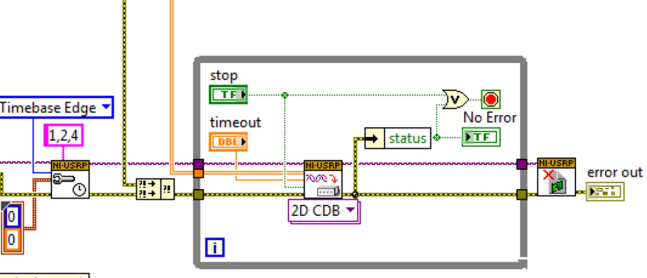
The block diagram of the usrp_rxrf_trigger_and_capture.vi subVI is given in Figure 8. As can be seen from Figure 8, the subVI captures a particular number of samples (80k for this example) and compares them to the given threshold to detect the presence of the transmitted signal. When the received signal samples are above the threshold, the subVI
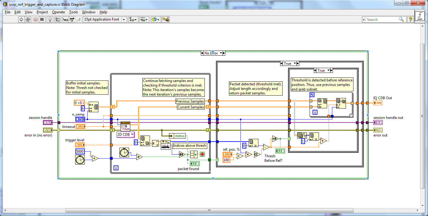
Figure 8: Block diagram of the usrp_rxrf_trigger_and_capture.vi
returns the IQ samples and a packet found flag. The IQ samples are then passed through matched filtering and oversampling operation (Figure 7). The processed IQ samples along with all the training parameters from the front panel and the calculated pilot signal positions are then fed to the mimo_ofdm_rx.vi subVI to get all six demodulated data streams. The usrp_mimo_rx.vi also presents the received packet streams and the demodulated QAM constellations to justify successful receiver operation. The block diagram of the mimo_ofdm_rx.vi is given in figure 9:
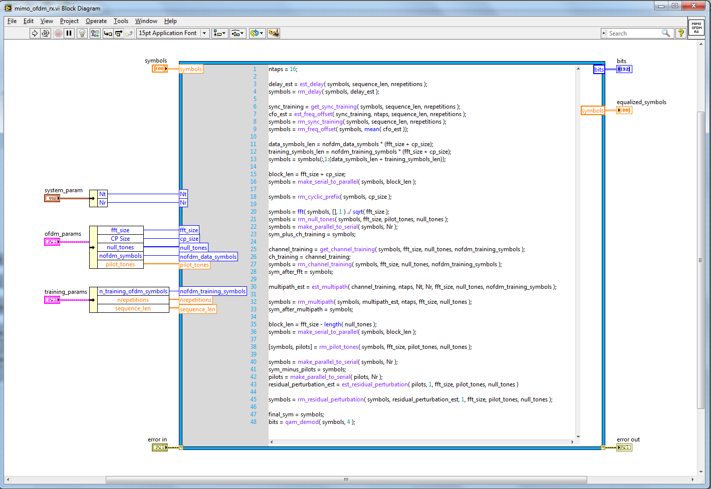
Figure 9: Block diagram of the mimo_ofdm_rx.vi
Results
Figure 3 shows the six RX signal constellations from a test run of the 6x6 MIMO system running on twelve NI USRP transceivers. The receiver addresses the impact of different channel impairments such as time delay, carrier frequency offset, multipaths, and residual channel perturbation by estimating and correcting them through appropriate signal processing operations. This image shows that the receiver works successfully.
Additional Resources
- J. W. Massey, J. Starr, Seogoo Lee, Dongwook Lee, A. Gerstlauer, and R. W. Heath Jr. Implementation of a real-time wireless interference alignment network. To appear in the Proc. of the Asilomar Conference on Signals, Systems and Computers, 2012.
**Please cite this paper if you want to build on this code and publish something with it.
- Mark as Read
- Mark as New
- Bookmark
- Permalink
- Report to a Moderator
I didnt have a look at it yet, but I wanted to know if I can reduce it to a SISO or 2x2 or 2x1 MIMO system ????
many thanks
- Mark as Read
- Mark as New
- Bookmark
- Permalink
- Report to a Moderator
The m-file code is only written for matched MIMO Tx Rx pairs. We've expanded it from 2x2 to 8x8 very successfully. The posted code defaults to the configuraiton of 6x6.
- Mark as Read
- Mark as New
- Bookmark
- Permalink
- Report to a Moderator
Could the first one run? I think there are some errors in the program, or I have made some mistakes?
- Mark as Read
- Mark as New
- Bookmark
- Permalink
- Report to a Moderator
Hi~
How to implement Interference Alignment function in this document?
- Mark as Read
- Mark as New
- Bookmark
- Permalink
- Report to a Moderator
http://www.profheath.org/research/interference-alignment/mimo-ofdm-interference-alignment-testbed/
The above link describes the testbed. This code is just the foundation.
- Mark as Read
- Mark as New
- Bookmark
- Permalink
- Report to a Moderator
The code was run and tested prior to posting. Having at least 4 USRP and 2 MIMO cables is required.
- Mark as Read
- Mark as New
- Bookmark
- Permalink
- Report to a Moderator
Hi,
I am looking into the code details. I am quite confused about how the delay removal is implemented. Why not use a match filter to do the correlation? The implementation here uses circular shifts instead.
Thank you!
- Mark as Read
- Mark as New
- Bookmark
- Permalink
- Report to a Moderator
Dear All,
I try this code, but I have some problem. The code has some errors. They are :
1. MathScript Node 'MathScript Node' (add_pilot_tones) : User-defined function contains error
2. MathScript Node 'MathScript Node' (make_channel_training) : User-defined function contains error
Anybody can help me??
Thanks a lot
Hendy
- Mark as Read
- Mark as New
- Bookmark
- Permalink
- Report to a Moderator
Hi,
I am newbie in this field. I have tried the 6x6 MIMO example and change it to 2x2 MIMO (by using combination of 4 USRP and 2 MIMO cable). However it occured an error that almost similar to Hendyb problem.
Hope you guys can guide me regarding this matter.
Thank you.
Rushidi
- Mark as Read
- Mark as New
- Bookmark
- Permalink
- Report to a Moderator
Hi,
I met some error before, but now it's ok. I think some function need to be changed, but it depends how to use it. my email is 2507042769@qq.com, we can discuss about it if you want.
Regards
Alvin
- Mark as Read
- Mark as New
- Bookmark
- Permalink
- Report to a Moderator
Hi,
I'm testing the code for 2x2 setup and I got error at rx part as follow:
Error -90032 occurred at Error in function signal at line 4 column 19: The indexes are out of bounds for the variable you specified.
C:\Users\User\Downloads\AFF540DC.Unpacker_v7353qx4kg3sa!App\6x6 MIMO OFDM_old(1).zip\mathscript\training\get_sync_training.m
Possible reason(s):
LabVIEW: The indexes are out of bounds for the variable you specified.
Is there any part that I need to change in the scipt file to avoid the error?
Look forward for your reply. Thanks
Singapore (65) 6226 5886 | Malaysia (60) 3 7948 2000 | Thailand (66) 2 298 4800
Philippines (63) 2 659 1722 | Vietnam (84) 28 3911 3150 | Indonesia (62) 21 2783 2355
- Mark as Read
- Mark as New
- Bookmark
- Permalink
- Report to a Moderator
Hi,
I am also getting the same error "the indexes are out of bounds" error in the get_sync_training.m Mathscript file. It looks like the time delay in the signal estimated by est_delay.m is a large value and therefore when the time delay is removed using rm_delay, it ends up removing a large chunk of the signal. This results in errors in the subsequent step which is get_sync_training becase most of the signal has been removed in the previous step. Is there perhaps another way to estimate the delay in the signal to work around this issue?
Thanks
- Mark as Read
- Mark as New
- Bookmark
- Permalink
- Report to a Moderator
Please try increasing the number of samples to acquire per buffer to a larger number. I believe the issue is a partial OFDM symbol is being passed into the processing part of the VI.
Regards,
Erik
- Mark as Read
- Mark as New
- Bookmark
- Permalink
- Report to a Moderator
Thanks Eric, reducing the IQ rate seems to do the trick. Now the code seems to be running fine but the constellation diagrams are blank. I have this same problem with the usrp_nxn_mimo_rx.vi as well. In the case the stream packet graphs update while the constellation graphs remain blank. I'm not sure why this is.
Thanks.
- Mark as Read
- Mark as New
- Bookmark
- Permalink
- Report to a Moderator
Hi Erik,
1)I'm testing the code for 2x2 setup but the same error still occur. In your opinion, why the error is still came out? I used IQ rate =1M and number of samples also 1M . I also changed the delay to 100ms and time out to 1000.The constellation diagram is better which is show the QPSK diagram. Is the error bring the problem during transmission or we can just ignore the error since the constellation diagram already appear?
(for 6x6 MIMO OFDM_old.zip file)
2) In 2nd script, I also testing the code for 2x2 setup (by increasing the time out & decreasing the delay). There is no error at TX and RX and the packet received by RX continuosly. However the constellation diagram not appear at TX and RX. How to overcome this problem?
(For MIMO OFDM for USRPs.zip file)
Your prompt reply is much appreciated.
Thanks
Regards,
Mardiah
- Mark as Read
- Mark as New
- Bookmark
- Permalink
- Report to a Moderator
I thought that reducing the IQ rate and increasing the number of samples per fetch would fix the issue but I'm still having errors in the training phase of the IA code. The code runs into an index error in the est_freq_offset Matchscript. I tried using various IQ and number of samples per fetch combinations but none of them seemed to work. Are there specific values that have worked for someone else?
- Mark as Read
- Mark as New
- Bookmark
- Permalink
- Report to a Moderator
Hi Mr Erik,
I want to ask about this example. How to change modulation from 4QAM to 8QAM or 16QAM?
Thanks a lot
- Mark as Read
- Mark as New
- Bookmark
- Permalink
- Report to a Moderator
Hi ErikL,
I am facing a problem while connecting usrp to a host PC using NETGEAR 8-port fast ethernet switch FS208.
After connecting usrp devices to a switch the NI Configuration utility won't detect the devices, please help me to sort out this problem.
- Mark as Read
- Mark as New
- Bookmark
- Permalink
- Report to a Moderator
I want evavluer the perfomance of MIMO 4 * 4 and 8 * 8 lte on labview with the simulation. I need the equipment ?
- Mark as Read
- Mark as New
- Bookmark
- Permalink
- Report to a Moderator
I want to evavlue the perfomance of MIMO 4 * 4 and 8 * 8 lte on labview with the simulation. I need the equipment ?
- Mark as Read
- Mark as New
- Bookmark
- Permalink
- Report to a Moderator
Maybe someone can help me with MIMO 2x2 and Fast OFDM? Please
- Mark as Read
- Mark as New
- Bookmark
- Permalink
- Report to a Moderator
I am having a problem on niUSRP Write Tx Data (2D CDB).vi<ERR> Packet had timestamp that was late (or too early). Please someone help me.
I am using Labview 2013
USRP 2920
I am doing MIMO 2x2
I try to up the timeout already.
The frecuency on PpsIN and RefIN is 10Mhz?
- Mark as Read
- Mark as New
- Bookmark
- Permalink
- Report to a Moderator
Now It is working i just put it on channel over SET TIME numbers 0,1 and over Write Tx DAtA too on channels 0,1; also on next time base edge i change to Now.
- Mark as Read
- Mark as New
- Bookmark
- Permalink
- Report to a Moderator
Hi!
Does this implementation has:
1. Channel precoding at 6 Tx antennas after pilot training signal is sent by Rx antennas in UL?
2. Does it use TDD kind of switching at TX1 and TX2 of correspoding USRP?
- Mark as Read
- Mark as New
- Bookmark
- Permalink
- Report to a Moderator
Hello! Hopefully this will answer your questions:
- Each of the transmitter USRPs use OFDM parameters to create null tones and pilot tones, which are used to add channel training and synchronization training to the transmitted signals. On the receiving end, the RX USRPs identify null tones and pilot tones from the OFDM parameters and can then use these tones to estimate and remove frequency offset, time delay, effects of multipath, and residual perturbations in the received data. Once these impairments have been addressed, the RX USRPs can remove the pilot tones and null tones from the signal altogether. So for clarification, both the RX and the TX VI's make the pilot tones and null tones based on the OFDM parameters in their front panels.
- TX1 and TX2 are actually on different daughterboards and transmit at the same so there is not any switching occuring between these two channels.
Applications Engineer
National Instruments
- Mark as Read
- Mark as New
- Bookmark
- Permalink
- Report to a Moderator
To answer your second question, TX1 and TX2 are actually on different daughterboards and transmit at the same so there is not any switching occuring between these two channels.
Applications Engineer
National Instruments
- Mark as Read
- Mark as New
- Bookmark
- Permalink
- Report to a Moderator
hello!
Does anybody know that when i open the code(for comm version) with labview communication, it tell
me that the load error and don't let me open it.
- Mark as Read
- Mark as New
- Bookmark
- Permalink
- Report to a Moderator
I am designing 2*2 MIMO using USRP 2952. I need to do beamforming at Transmitter. Do we have any already implemented block in either of the projects/examples which does channel estimate and precoding?
- Mark as Read
- Mark as New
- Bookmark
- Permalink
- Report to a Moderator
I am designing 4*2 MIMO using 3 USRPs (TWO for transmitter and 1 for receiver). I dont have access to external clock and pps trigering. I read about using PPS and REF IN/OUT ports at back pannel of USRP. Can I make connections using SMA cable to connect PPS trigger of one USRP(As TX) to PPS in of 1(another 2952 as TX for 4*4) and connect it's PPS out to that of Recever USRP PPS in? Similalry connect clock reference out with IN of other. Please share architecture of synchroizing multiple USRPs for MIMO design using SMA cable.
- Mark as Read
- Mark as New
- Bookmark
- Permalink
- Report to a Moderator
Yes. Are you doing SU-MIMO or MU-MIMO?
Regards,
Erik
Sent from mobile device.
- Mark as Read
- Mark as New
- Bookmark
- Permalink
- Report to a Moderator
Dear Erik,
For both 2*2 and 4*2 or say 2*1 and 4*1, MIMO Transmitter with 2 or 4 antennas and one user with one or two antenna.
For first experiment it will be MIMO trasmitter with 2 (single USRP 2952) and 4 antenna(designed by connecting 2 USRP 2952).
My goal is to test beamforming and insure users other than the ligitimate user(having predefined PN sequence/ training sequence) does not receive information.
I need to design precoder at beamforming unit for that. This needs tight synchronisation.
Please let me know the architure of configuration using SMA cables.
And if there are blocks for channels estimation and precoding vector design in any of the USRP projects please let me know.
Regards,
JP
- Mark as Read
- Mark as New
- Bookmark
- Permalink
- Report to a Moderator
Hi everybody, I try to do the 2*2 MIMO ! In the program, I turn off the other antenna source, and keep two antennas work in Tx
,choosing the clock souce be internal, and Rx vice versa...but i met the problem when i run the program, it will stock in an infinitive while loop, never break out!!
My problem is below:
1.why the problem happening!!?
2.Are there any wrong tip in my initial setting??!
- Mark as Read
- Mark as New
- Bookmark
- Permalink
- Report to a Moderator
hi, I can't open the project with labview communicaiton file. It shows loading error. Does any body know the reason? Thank you.
- Mark as Read
- Mark as New
- Bookmark
- Permalink
- Report to a Moderator
Maybe it is because first you must to charge all mathscript programs to labview
- Mark as Read
- Mark as New
- Bookmark
- Permalink
- Report to a Moderator
Hi, Richard
Thank you for the answer. But when I try to open the project, it shows the format is invalid. And how can I charge the mathscript programs to labview communication.
Thank you very much.
- Mark as Read
- Mark as New
- Bookmark
- Permalink
- Report to a Moderator
Hi NovaQ, as you can see in the introduction "The material below is relevant to both of these versions but in order to get these two versions running you need to have LabVIEW 2015 and LabVIEW Communications 2.0 (respectively) installed."
- Mark as Read
- Mark as New
- Bookmark
- Permalink
- Report to a Moderator
@msohul wrote:
...NI USRP RIO devices have two daughterboards, so that each device can support 2 RF channels. Ultimately, this feature allows us to implement a 6x6 MIMO System with 6 USRP RIO devices.
Hi everyone, I'm a newbie with using NI USRP 2953R and LaVIEW Comm 2.0.
I wonder whether I can use this code to implement 4x4 MIMO using 2 USRP devices (each device has 2 RF channels with 2 TX and 2 RX antenna?
Why don't we use 3 USRP RIO devices to implement 6x6 MIMO system instead of 6 devices as msohul said?
- Mark as Read
- Mark as New
- Bookmark
- Permalink
- Report to a Moderator
hi sir can you give me your mailed ,thank u
- Mark as Read
- Mark as New
- Bookmark
- Permalink
- Report to a Moderator
Hello everyone, could you help me with the parameters of I / Q, number of samples and other parameters to implement MIMO 4x4.
Thank you
- Mark as Read
- Mark as New
- Bookmark
- Permalink
- Report to a Moderator
Hello ErikL,
You could help me with the parameters, configurations and channels needed to implement this program in MIMO 4x4 please be very helpful.
- Mark as Read
- Mark as New
- Bookmark
- Permalink
- Report to a Moderator
Hi ErikL,
You can help me with the parameters in TX and Rx so that MIMO 4x4 works
Thank
- Mark as Read
- Mark as New
- Bookmark
- Permalink
- Report to a Moderator
Hello everyone,I have some problem with those codes.I was run the project In the MIMO OFDM with USRPs.zpi,but the constellation diagrams are mess.Is't something wrong with the codes?Or some mistake in my work?
- Mark as Read
- Mark as New
- Bookmark
- Permalink
- Report to a Moderator
Hi 谭家 易, I have a similiar problem try 4x4 MIMO but the constellation diagrams are just noise. The project works very well for 2x2 MIMO but at the moment of passing it to 4X4 MIMO gives error knows some kind of parameter or configuration that must be made for its operation?
- Mark as Read
- Mark as New
- Bookmark
- Permalink
- Report to a Moderator
I also do not see the constellation points although the system appears to be working. Is there any fix for that?
- Mark as Read
- Mark as New
- Bookmark
- Permalink
- Report to a Moderator
Dear Erikl,
Iam trying to run usrp_mimo_tx.vi and usrp_mimo_rx.vi in LabVIEW for a 2x2 MIMO using two USRP RIO 2942 devices (two transmit antenna from the first device and two receive antenna from the second device). The transmitter is working fine with me but the I have errors in the receiver. The error is: Error in function symbols at line 13 column 11: The indexes are out of bounds for the variable you specified.
below is the capture picture for the TX and RX results. Also I tried to run the code using one RIO device (two transmit antenna and two receive antenna from the same device) but I got again error in the receiver side.
NOTE: I set the clock and frequency source to internal because Iam not using octoclock.
your help and reply will be highly appreciated.
Thank you
Tasnim


- Mark as Read
- Mark as New
- Bookmark
- Permalink
- Report to a Moderator
Dear Mr/ ErikL
many thanks for your effort , i followed all your steps the VIs are working and during the run i didn't got any graphs in the constellation diagrams can you support me in this issue .
- Mark as Read
- Mark as New
- Bookmark
- Permalink
- Report to a Moderator
I use four usrp-2922 to form a 2x2version using this application.But i met below error, i have no parameters to change...Many thanks for you.
usrp_nxn_mimo_rx.vi -> ofdm_rx.vi -> demod_ofdm_symbols.vi -> make_serial_to_parallel.vi
Message:
Expected signal length could not be evenly distributed into blocks.
Signal Len:2545
Block Len:160
or
usrp_nxn_mimo_rx.vi -> ofdm_rx.vi -> demod_ofdm_symbols.vi -> rm_cyclic_prefix.vi
Message:
Expected parallel signal block length exceeded the cyclic prefix size.
