- Document History
- Subscribe to RSS Feed
- Mark as New
- Mark as Read
- Bookmark
- Subscribe
- Printer Friendly Page
- Report to a Moderator
- Subscribe to RSS Feed
- Mark as New
- Mark as Read
- Bookmark
- Subscribe
- Printer Friendly Page
- Report to a Moderator
Design & Implementation of a Building Automation System Working in Stealth Mode
BY
PhD Qutaiba Ibrahim Ali, Eng. Bashar Abdul Aziz
University of Mosul, Iraq
Products Used:
LabVIEW TM, PCI-6251M TM DAQ, LabVIEW TM drivers for parallel port, NI Electronics WorkBench Ver.10 (NI Multisim)
The Challenge:
Designing & Implementing a building automation system using already installed network resources
The Solution:
NI products integrates successfully with custom made DAQ and act as the main system controller in a flexible and efficient manner.
Abstract:
Traditional implementation of buildings automation systems depend on their own network devices and media. This concept is true if no network was installed before. However, if an already installed network exists, the situation is different. In this paper we suggest the use of an already installed network to carry measurement and control data of a centrally controlled air conditioning system. Our automation system will share the same network devices, transmission media and end points (i.e., PCs) with the traditional users of the network. The main idea of this project is the transparent integration of an automation system to the existed network while adding minimum extra load on it. We make use of the PC nodes distributed in the building to be the bridge of our system without affecting its performance or disturbing their users. In order to achieve this goal, we build our own programmable data acquisition card based on 8051 microcontroller, developing a LABVIEW based driver for this DAQ which forward the measured data to a LABVIEW based central control and monitoring PC.
1. Introduction:
The term Building automation refers to an intelligent network of programmable controllers and software that monitors and controls mechanical heating, ventilation and air conditioning equipment, and indoor and outdoor lighting in a building. The primary function of a building automation system or energy management system is to increase the efficiency of a building and reduces energy and maintenance costs. Building Automation systems optimize the performance and maintenance of multiple building control systems including;
•Heating, ventilation, and air conditioning (HVAC) – These systems include central plants, air handling units, package units and fan coils.
•Lighting systems – including indoor and outdoor systems.
•Metering systems – including electrical meters, gas meters and BTU meters.
There are two major components to building automation systems; the user interface software and the controller. The user interface is typically a computer based graphical software application that allows the user to interface with the system and provides the user full control over the building automation system. A controller is an electronic device that monitors and changes the operations of a specific system. The operational conditions include output variables of the system which can be affected by adjusting certain inputs. The communication between these two components is achieved through special and dedicated network resources.
In this paper we decide to take a different approach. The buildings which are used as offices for companies, hospitals, universities, schools, etc…, have installed their computer network to carry data for their own businesses. Also, almost every room in these buildings has at least one PC connected to the buildings Local Area Network (LAN). These network resources can be used as the infrastructure for the building automation system as well.
2. Description of the Current Work
The buildings automation concept presented in this paper provides a reasonable and cost effective solution. The main structure of the suggested system can be shown in Figure (1).
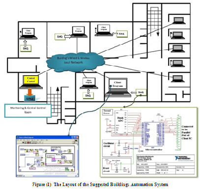
The main components of the system are: a programmable input Data Acquisition Cards (DAQ), a Labview based client program, a Labview based central control software and output Data Acquisition Card (DAQ). The actions of these components can be explained as follows:
1. The input Data Acquisition Cards (DAQ) has the responsibility of gathering the required measured quantities from the environment. The word “Stealth mode” can precisely describe the operation of this card. Our idea state that we make use of the ordinary PCs, distributed within the building, to be the bridge between the input DAQ and the building’s local network. However, this task must be achieved while adding minimum load on these PCs and the local network. What we need here is an intelligent DAQ capable of processing the data then selecting the non redundant one and passing them to its computer through the bus between them. Also, this DAQ must be programmable in order to cover the different needs and to serve against multiple conditions. In order to realize these needs, we decide to build our own prototype DAQ (this card was designed and checked using NI Electronics WorkBench Ver.10). The heart of the card was an 8051 microcontroller connected (via ADC) to a thermal sensor from one side and to the computer bus (through parallel port) from the other side. The memory of this microcontroller was filled with different subroutines (to reflect the different situations) and one of them is chosen every time to achieve certain task. The card is reconfigured remotely by the administrator over the building’s LAN, making use of the host IP to be reachable. In order to guarantee the continuity of its functioning, the card keeps its work even if the PC was in standby mode.
2. The second component in our system was the client program. This Labview base software represents the driver of the input DAQ. This executable software is installed on the PC and reads the data coming from the parallel port (i.e., the input DAQ), then converting them to an appropriate network packet to be sent to the central control server using UDP protocol. This software has another task during the DAQ’s reconfiguration process, in which it passes the administrator commands to choose one of the programs stored in the microcontroller’s memory.
3. The last part of the system is the central control & monitoring room. It consists of a networked PC supplied with a Labview based program and connected to a PCI-6251M DAQ card. This server reads the data coming through the building’s LAN from the various input DAQs, monitors them on its GUI and gives the proper commands to the central air conditioning system via PCI-6251M DAQ card. As seen in Figure (2), the GUI provides both monitoring and programming functions to its user. The remote DAQs can all be reconfigured with the same program or individually using different programs.

Figure(2): Details of the Central Control & Monitoring Software
Our implementation of the system was very easy and timely efficient. We connect the input DAQ to few PCs on the second floor of computer engineering department/ Mosul university campus, and then we supply these nodes with the client program. After awhile, we began to receive the data from these nodes which affect on the decision taking by the server towards the central air conditioning system. Also, the reprogramming task was very efficient and needs little efforts. Our measurement on the computer’s CPU (using Windows Task Manager) shows that the maximum load afforded by the input DAQ does not exceed (2%). On the other hand, the load provided to the network was less than (0.5%) of its bandwidth. This result proves that the suggested method adds minimum load on both the network and the end nodes.
The main factor behind the success of this project was the flexibility provided by NI products. The first point to mention here is the ease in building the driver program of our custom made DAQ and the optimistic way to connect it to the network. The second point is the ease and efficiency given by the Labview to build the central control GUI and its control function. Also, the virtual design of our prototype DAQ using NI Electronics WorkBench Ver.10 and the tests we made prior to its realization was very useful in choosing the proper circuit components and their values.
