- Subscribe to RSS Feed
- Mark Topic as New
- Mark Topic as Read
- Float this Topic for Current User
- Bookmark
- Subscribe
- Mute
- Printer Friendly Page
hi ,need some help with grid tied inverter+grid
06-23-2014 07:28 AM
- Mark as New
- Bookmark
- Subscribe
- Mute
- Subscribe to RSS Feed
- Permalink
- Report to a Moderator
hi
I was using simulink up to now and I would like to use LV for my simulations.I am not experienced with the program
1)
without the
Hardware Implementation and while I will import files that contains measurements
would LV be powerful tool as simulink?
2)
I would like to know where can I get the model of the following:
Complete System Simulation of a 3-Phase Inverter Using NI Multisim and LabVIEW
http://www.ni.com/white-paper/13720/en/
file is attached
3)
and how can I find a model for simulation for agrid+transformer (22KV and transfor of 630Kva)
Thank you help will be appreciated
06-24-2014 03:14 AM
- Mark as New
- Bookmark
- Subscribe
- Mute
- Subscribe to RSS Feed
- Permalink
- Report to a Moderator
You might find this answer helpful:
https://decibel.ni.com/content/message/74907#74907
The Power Electronics Design Guide has a wealth of information, including probably the simulation you mention in point 2.
06-25-2014 12:44 PM
- Mark as New
- Bookmark
- Subscribe
- Mute
- Subscribe to RSS Feed
- Permalink
- Report to a Moderator
Agreed. There are 3-phase inverter + line reactor filter models included in the Power Electronics Design Guide.
Also see the new NI Power Electronics Control Design V Training Workshop for the latest 3-phase inverter control code and Multisim models (including switching/conduction losses and temperature in the case of the 3-phase induction motor co-simulation).
For the older Power Electronics Design Guide examples, keep in mind that they were written before the release of the LabVIEW FPGA Desktop Execution Node. Now you simply right-click on the FPGA target, set it to simulation mode, and you can run the FPGA control application in simulated time that's automatically step-by-step synchronized in closed loop with the Multisim power electronics simulation, as shown below.
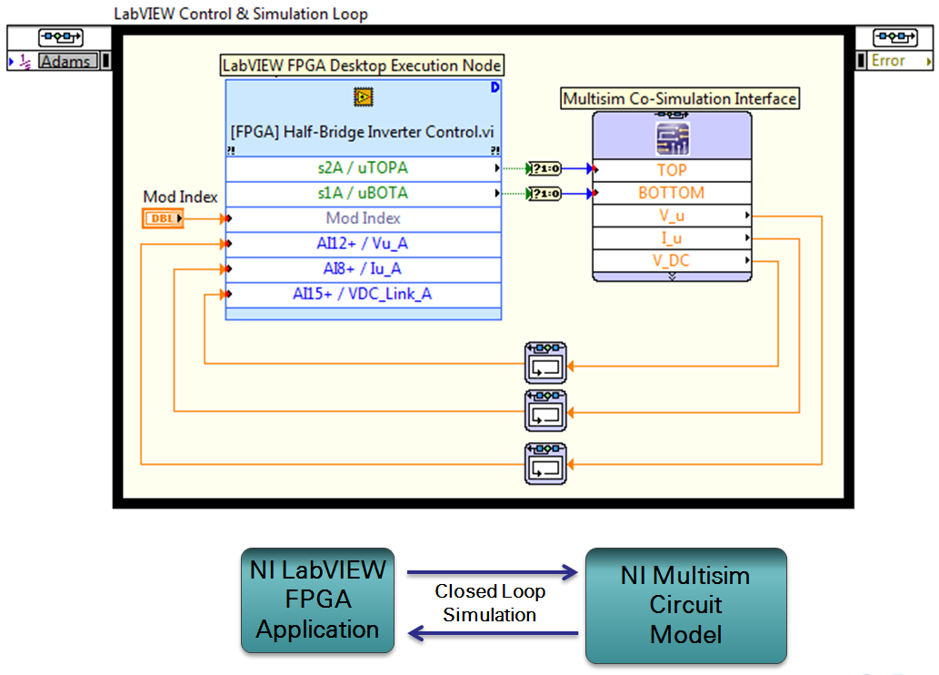
To enable high fidelity co-simulation, the LabVIEW FPGA Desktop Execution Node interfaces to the LabVIEW FPGA Application while the Multisim Co-Simulation Interface connects to the power electronics circuit model. A desktop testbench application is shown above.
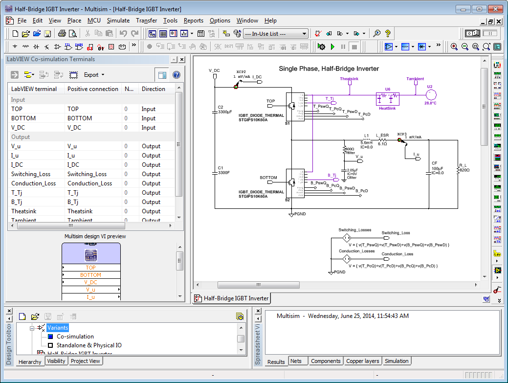
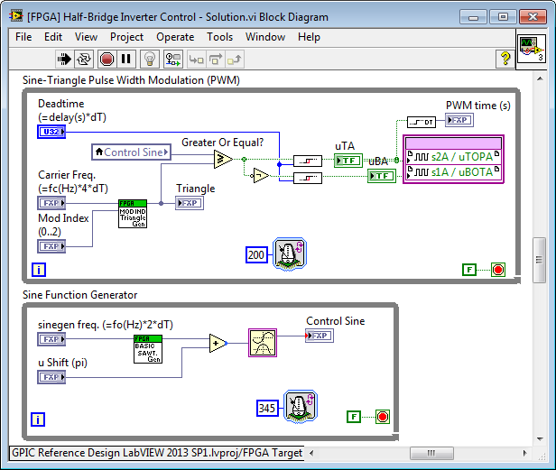
The Multisim power electronics circuit (top image below) and LabVIEW FPGA control application (bottom image below) are co-simulated with a common sense of simulated time.
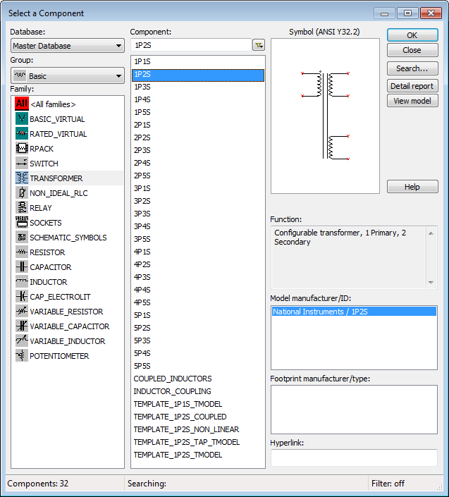
Regarding your #3 question on grid source and transformer models, in Multisim right-click on the schematic, go to Place Component, and then browse to Sources where you will find 3-Phase Wye and 3-Phase Delta Sources. For transformers, go to Basic>TRANSFORMER, as shown below.
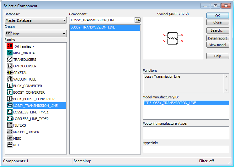
For transmission lines, go to Misc components, as shown.
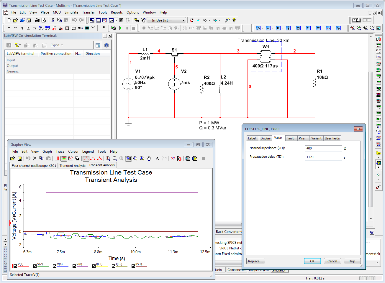
I've attached a few examples that demonstrate these components.
1. Transmission line with recloser circuit breaker. The recloser vacuum breaker switch closes at 7 milliseconds, reconnecting power to the 30 km transmission line. Study the transient effects at each end of the transmission line. The grid source is 20 kV rms.
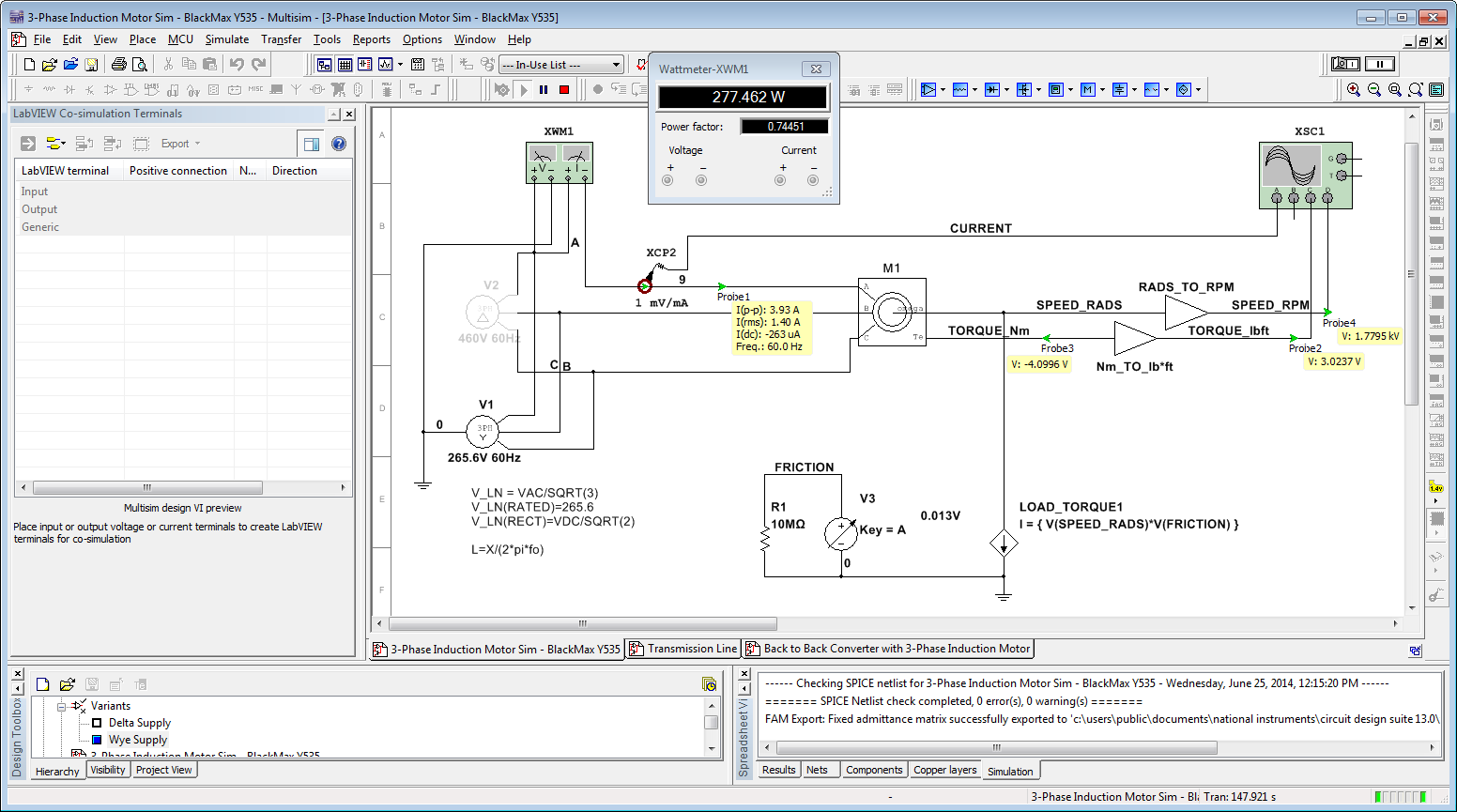
2. The three-phase delta and wye grid sources are demonstrated by this 3-phase squirrel cage induction motor simulation. Notice that the simulation results are a reasonably good match to the BlackMax Y535 motor datasheet parameters (power factor, phase current, speed/slip) when the motor is operated at the rated torque (3 lb*ft) and under no load. (The motor datasheet parameters are normally a bit pessimistic, meaning more current and slip, than a simulation so the vendor can account for manufacturing tolerances.) To change the load torque, move the slider or use the A key.
To change the grid from a 3-Phase Wye source to a 3-Phase Delta source for the grid, change the circuit Variant (see bottom left corner of screenshot or go to Tools>Variant Manager). Note that the motor response does not match the datasheet when using a Delta-connected grid source, as we would expect.
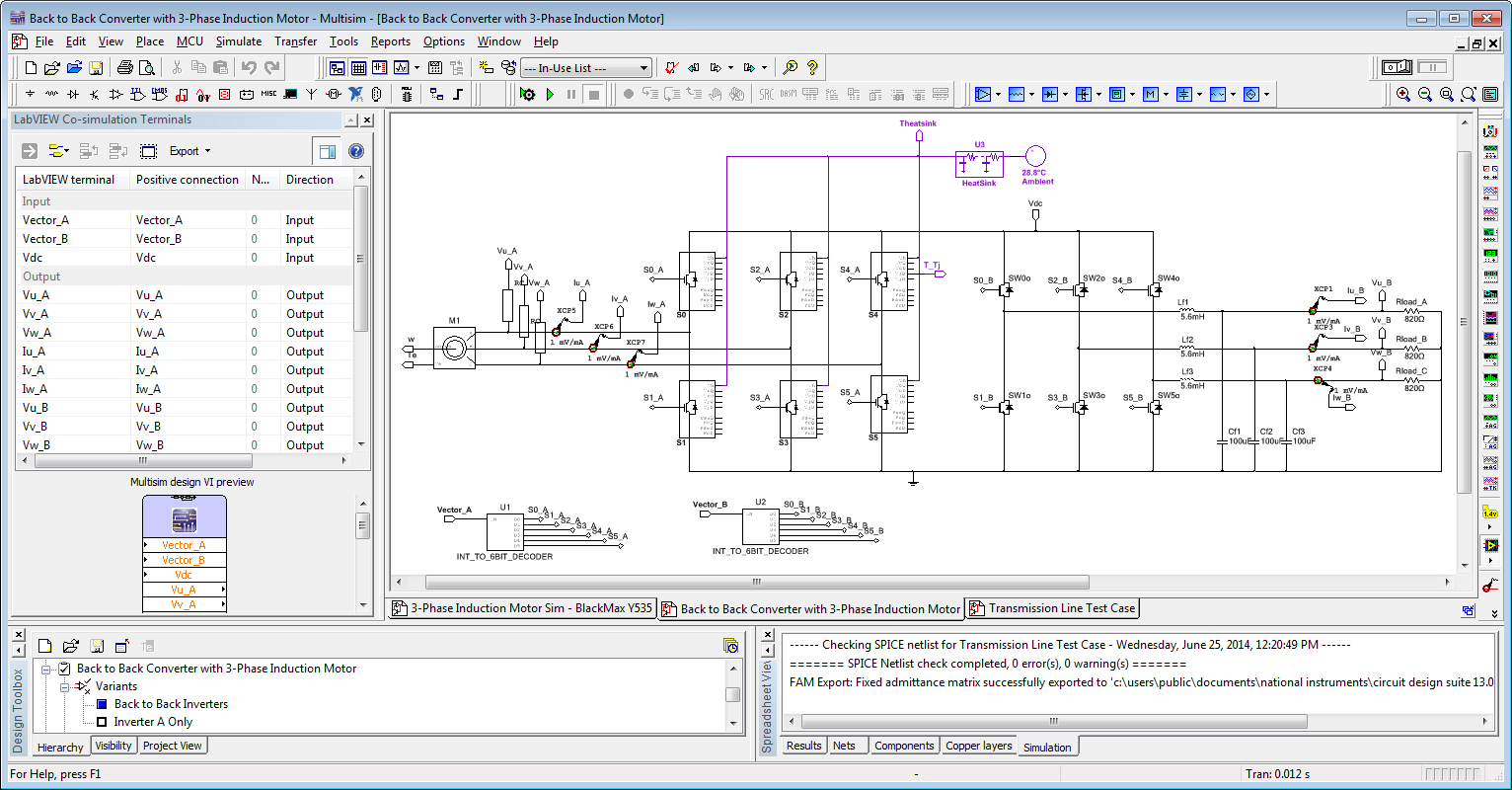
3. Two types of 3-phase inverter models are demonstrated with the circuit below. This circuit topology matches the mini-scale power converter training/research board (an open source circuit design you can modify to meet your R&D needs), assuming the DC link contactor is closed.
On the left (inverter A) we have a MotorSolver 3-phase induction motor connected. For this 3-phase inverter, we are modeling the switching/conduction losses and transient temperature of the STGIPS10K60A six-pack IGBT intelligent power module. On the right (inverter A) we have a 3-phase line reactor filter connected, as is common for grid tied power converters. For this 3-phase inverter, we are using basic IGBT/Diode model that includes turn on voltages, forward voltage drop and conduction resistance but no loss/thermal modeling. For a co-simulation example, see the NI Power Electronics Control Design V Training Workshop code.
All three of these Multisim simulation models are attached. BTW, if you are looking for a 3-phase transformer let me know.
12-23-2014 01:35 AM
- Mark as New
- Bookmark
- Subscribe
- Mute
- Subscribe to RSS Feed
- Permalink
- Report to a Moderator
For grid-connected inverter simulation, can I connect the ac source to the output of the inverter? When I did that, the grid current looked weird. But the same parameters worked on other simulation software. I didn;t find out an example with ac source connected. Thanks.
12-23-2014 07:22 AM
- Mark as New
- Bookmark
- Subscribe
- Mute
- Subscribe to RSS Feed
- Permalink
- Report to a Moderator
The output is also an AC source. If you connect them together, then you
must also synchronize the phase angle. Use one as a phase reference and
shift the other.
12-23-2014 10:48 AM
- Mark as New
- Bookmark
- Subscribe
- Mute
- Subscribe to RSS Feed
- Permalink
- Report to a Moderator
For co-simulation, I just set the phase of both the AC source and sin ref to be the same (zero for example). Have you tried to connect AC source and check the waveform?
03-20-2022 08:51 AM
- Mark as New
- Bookmark
- Subscribe
- Mute
- Subscribe to RSS Feed
- Permalink
- Report to a Moderator
Can you help me in the same?
