- Subscribe to RSS Feed
- Mark Topic as New
- Mark Topic as Read
- Float this Topic for Current User
- Bookmark
- Subscribe
- Mute
- Printer Friendly Page
Integrator Prolem
Solved!01-13-2016 10:03 AM
- Mark as New
- Bookmark
- Subscribe
- Mute
- Subscribe to RSS Feed
- Permalink
- Report to a Moderator
Hi,
I am trying to use the PID tools for only integrator purpose. But the output i am getting is not exact integration of input. For example if input is 4sinx then output does not come as 4 cosx.but some random phase shift and with differnt amplitude.
Also in the FPGA there is no PID with seperate entry for KP and KI. The PID in FPGA having KI dependent on KP. So to use it as a pure integrator is not possible.
Please help if possible.
Solved! Go to Solution.
01-13-2016 01:17 PM
- Mark as New
- Bookmark
- Subscribe
- Mute
- Subscribe to RSS Feed
- Permalink
- Report to a Moderator
As you mentioned, the PID control algorithm is not a pure integrator. Instead, you may want to use [FPGA] DiscreteIntegrator Trapezoidal Multichannel 01.vi. It is a pure integrator and is included in the open source power electronics IP library here:
C:\LabVIEW 2015\IP Cores\IP Cores - LabVIEW FPGA\HIL Solver\Polymorphic subVIs\[FPGA] DiscreteIntegrator Trapezoidal Multichannel 01.vi
It is also a multichannel IP core, so integrating multiple signal channels does not use any more FPGA resources (it only takes more calculation time).
Here are the control and indicator terminals for the trapezoidal integrator.
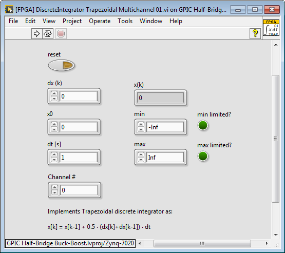
Inputs:
dx (k) is the floating point signal you want to integrate
x0 is the initial value that occurs on reset or if the integral value reaches Infinity (Inf), -Infinity (-Inf), or Not a Number (Nan)
reset is a true/false control the resets the integrator
dt is the timestep in seconds between calls to the IP core. This must be set to the correct time interval in seconds.
Channel # is the channel number integer that corresponds to the current dx (k) and x(k) values. The integration state values are held in a separate memory location for each channel.
min is the minimum value for the integrator output. If the integration exceeds this minimum value, the output will be limited to min and the min limited? indicator will be true.
max is the maximum value for the integrator output. If the integration exceeds this maximum value, the output will be limited to max and the min limited? indicator will be true.
Outputs:
x(k) is the floating point integrator value corresponding to Channel # and input dx (k)
min limited? indicates that the integrator value x(k) is being limited to min
max limited? indicates that the integrator value x(k) is being limited to max
Algorithm:
Implements Trapezoidal discrete integrator as:
x
Note: For a given sample rate, trapezoidal integrators provide better results for waveforms with harmonics compared to an Euler (RK1) integrators in my experience. However, if desired you can find an Euler (RK1) integrator in the IP library here: C:\LabVIEW 2015\IP Cores\IP Cores - LabVIEW FPGA\HIL Solver\[FPGA] DiscreteIntegrator RK1 Multichannel.vi.
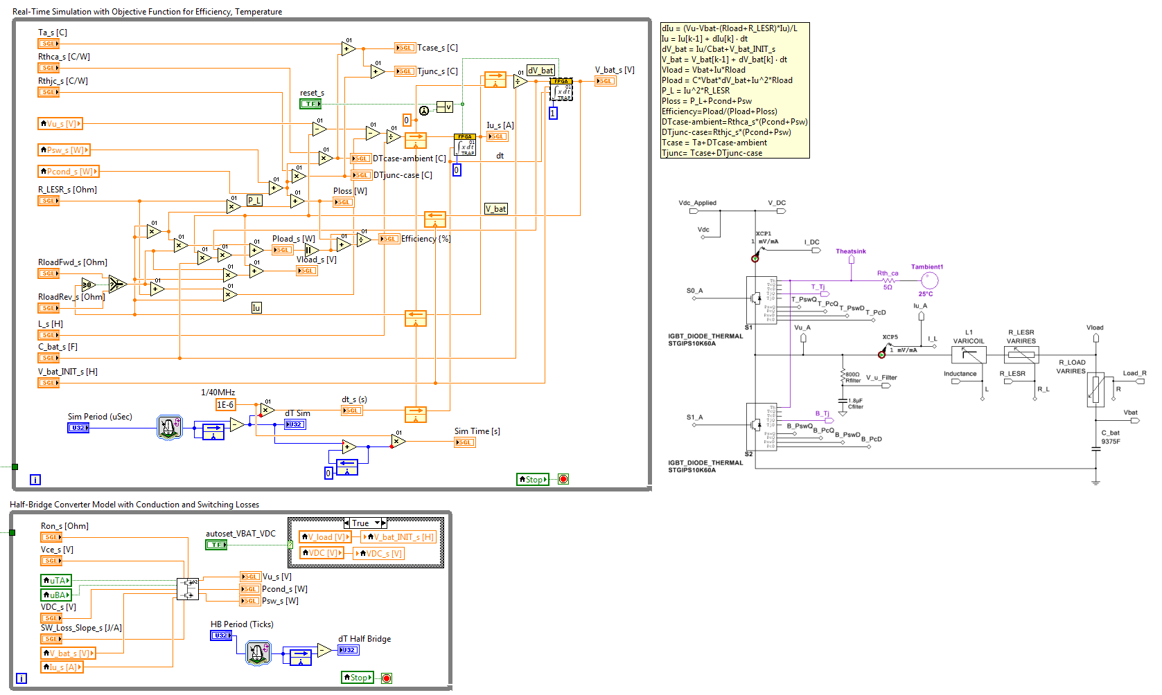
Example location and screenshot:
This example implements a real-time digital twin HIL simulation model for a half-bridge IGBT buck-boost converter including capacitive battery model with different charge and discharge resistances. The IGBT half-bridge model includes switching and conduction losses as well as a thermal simulation with zero delay observer for IGBT junction temperature that is used for active junction temperature regulation for improved reliability and power converter lifetime extension.
C:\LabVIEW 2015\GPIC\GPIC Half-Bridge Buck-Boost\Sensorless Maglev\FPGA\[FPGA 9607] NI GPIC Buck-Boost Energy Storage Converter.vi
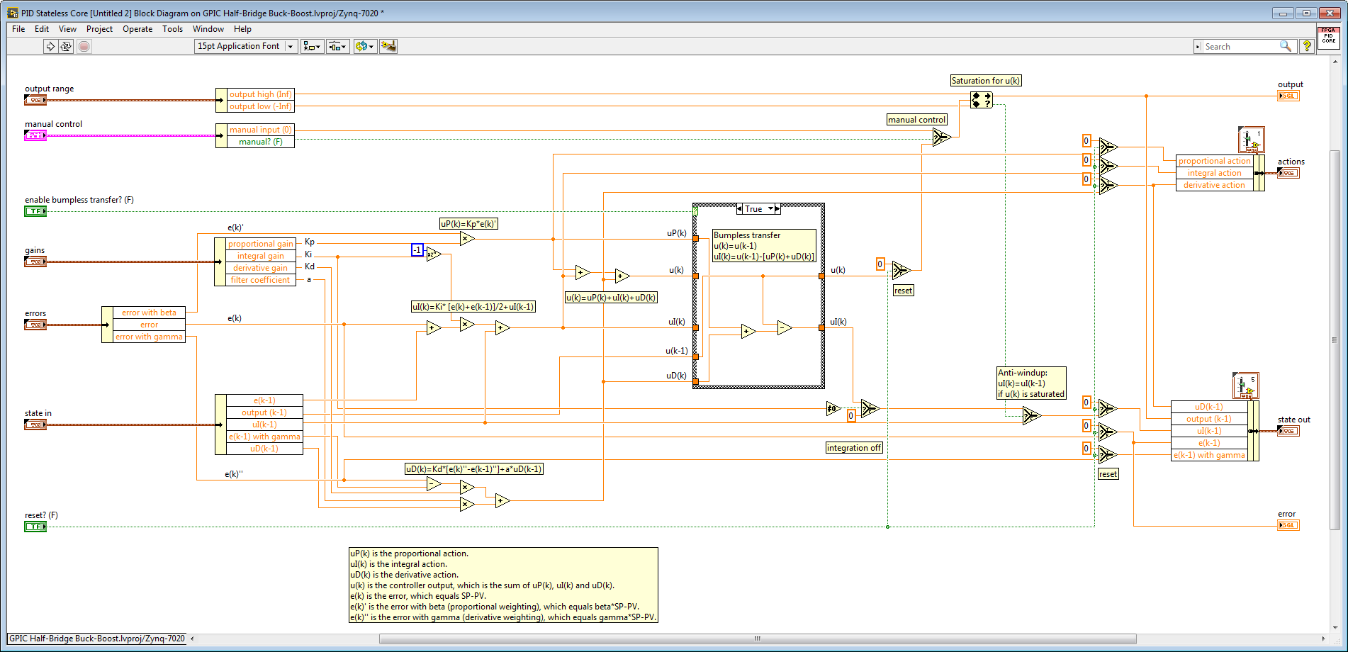
As a reference, here is the (open source) implementation of the integrator in the LabVIEW 2015 PID core that is included on the LabVIEW FPGA palette (FPGA Math & Analysis>Control). To access the embedded source code, right click on the internal subVIs and select Open Front Panel.
01-02-2019 11:11 AM
- Mark as New
- Bookmark
- Subscribe
- Mute
- Subscribe to RSS Feed
- Permalink
- Report to a Moderator
Thanks a lot. Is there any method to do it on host or RT. ?
