- Subscribe to RSS Feed
- Mark Topic as New
- Mark Topic as Read
- Float this Topic for Current User
- Bookmark
- Subscribe
- Mute
- Printer Friendly Page
Hysteresis control
Solved!10-06-2015 06:51 AM
- Mark as New
- Bookmark
- Subscribe
- Mute
- Subscribe to RSS Feed
- Permalink
- Report to a Moderator
Hi
I am trying to control my DC link voltage of capacitor by hyteresis control of 3 phase inverter connected to grid.Can somebody suggest that how to fire the IGBT by Pulse generated from the Hystereis band.
Solved! Go to Solution.
10-06-2015
09:32 AM
- last edited on
07-16-2024
08:46 AM
by
![]() Content Cleaner
Content Cleaner
- Mark as New
- Bookmark
- Subscribe
- Mute
- Subscribe to RSS Feed
- Permalink
- Report to a Moderator
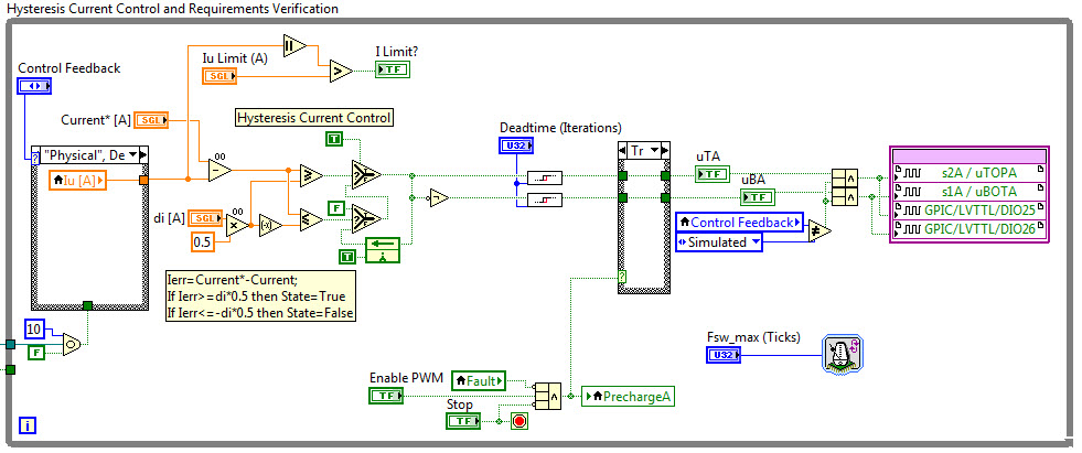
Here is an example of hysteresis current control for a single phase, which implements the following logic whereby "Current*" refers to the reference current setpoint and "Current" refers to the measured phase current. The "di" value determines the hysteresis band.
Ierr=Current*-Current;
If Ierr>=di*0.5 then State=True
If Ierr<=-di*0.5 then State=False
Notes:
1. When using the mini-scale SKiiP3 back-to-back converter rapid control prototyping system, you may wish to add the following logic to ensure that the upper half-bridge gate drivers remained charged:
If (Ierr<di*0.5)||(Ierr>-di*0.5) then State=State[k-1]
If dt>=dt_max then State=-State[k-1]
Explaination: A programmable timeout value "dt_max" is used to ensure that the output does not stay in a given state for longer than the timeout value. This is important when using the mini-scale SKiiP3 back-to-back converter rapid control prototyping system, because the STGIPS10K60A intelligent power modules require that the lower half-bridge is pulsed regularly (i.e. at least once per millisecond) in order to keep the gate drive boost converter for the upper half bridge charged. See application note for details.
2. To minimize the latency between the analog input sampling and updating of the digital hysteresis control output gate command signals, the execution of the hysteresis control loop is triggered (using the Wait on Occurence function in the hysteresis control loop above) after the current is sampled by the GPIC analog to digital converter and converted to engineering units (Amps). This synchronization of the timing is done using a LabVIEW FPGA Occurence. Here is a screenshot of the analog input loop where the Occurence is created (left side) and set (right side).

This code was developed for an E-I core transformer magnetic levitation control system. The screenshots above are from "FPGA\[FPGA] NI GPIC Buck-Boost Maglev Hysteresis Control v41.vi".
You can download the code from here.
10-06-2015 10:25 AM
- Mark as New
- Bookmark
- Subscribe
- Mute
- Subscribe to RSS Feed
- Permalink
- Report to a Moderator
Hi BMac,
Thank you for your help with this issue. I will try to emulate this in 3 leg inverter connected to grid.
10-27-2015 03:39 AM
- Mark as New
- Bookmark
- Subscribe
- Mute
- Subscribe to RSS Feed
- Permalink
- Report to a Moderator
If it could help, in 3-ph systems you could use a control strategy as
Lidozzi, A.; Solero, L.; Crescimbini, F., "Adaptive Direct-Tuning Control for Variable-Speed Diesel-Electric Generating Units," in Industrial Electronics, IEEE Transactions on , vol.59, no.5, pp.2126-2134, May 2012
Being the application grid-tied, rectifier modulation index is almost constant. Three simple PI controllers with parameters adaptation on the voltage loop. It provides constant bandwidth in all the converter operating range.
Adaptive tuning algorithm can run on the RealTime target with relaxed time-step, saving FPGA space.
01-02-2019 11:16 AM
- Mark as New
- Bookmark
- Subscribe
- Mute
- Subscribe to RSS Feed
- Permalink
- Report to a Moderator
Hi. I know it would be your research work but if possible can you please share any example code.
