- Subscribe to RSS Feed
- Mark Topic as New
- Mark Topic as Read
- Float this Topic for Current User
- Bookmark
- Subscribe
- Mute
- Printer Friendly Page
How to simulate the temperature, energy efficiency and lifetime of power electronics transistors in co-simulation?
06-15-2014 02:09 AM
- Mark as New
- Bookmark
- Subscribe
- Mute
- Subscribe to RSS Feed
- Permalink
- Report to a Moderator
Is there anyone know how to use thermal model from EPC in multisim? There is no thermal model for GaN FETs.
06-16-2014 10:10 AM
- Mark as New
- Bookmark
- Subscribe
- Mute
- Subscribe to RSS Feed
- Permalink
- Report to a Moderator
For years we have been working with lots of folks at OEM design teams and in the online developer community on the requirements for thermal and energy efficiency models for power electronics transistors in Multisim. This has been one of the top requested features among OEM design teams since cooling, energy efficiency, lifetime and cost are the top factors impacting any power electronics design. The primary design goals NI was asked to achieve include:
1. Quick estimation of steady-state temperature for sizing and thermal system design.
2. Accurate calculation of switching/conduction losses and transient thermals based on the exact custom/proprietary FPGA-based pulse width modulation and control scheme being developed by the design team.
3. Must be able to easily take data from the vendor datasheet and/or laboratory measurements on the devices and enter this in. (Vendors do not typically provide SPICE type physics based models).
4. The simulation model must be relatively fast. Don't overburden it by modeling physical characteristics that are not important.
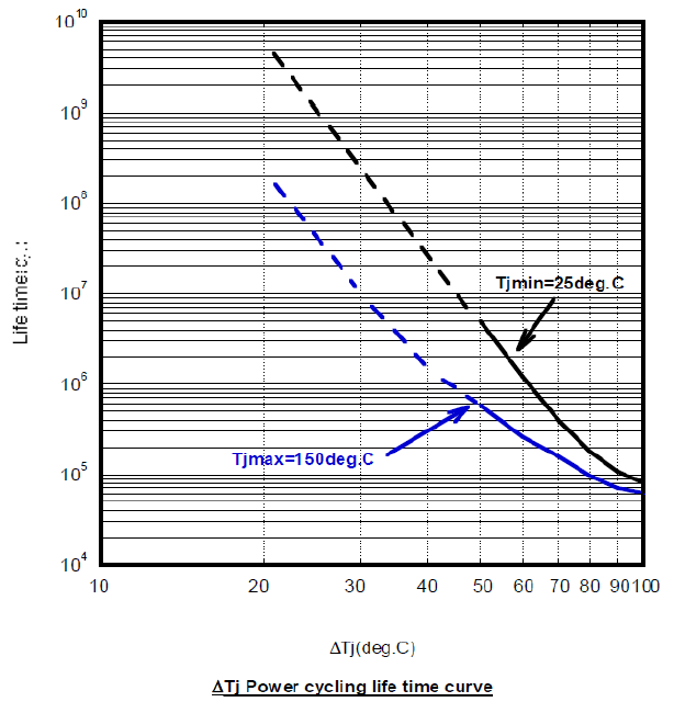
5. The thermal cycling data should enable us to estimate the expected transistor lifetime/lifecycle based on vendor data (example). Vendor Delta-Tj power cycling life time curves estimate how many times the temperature can be cycled before the transistor is expected to fail. It's a log-log relationship, so an IGBT that can survive 2.2 Million cycles of 20 degrees C may only be able to survive 50,000 cycles of 100 C.
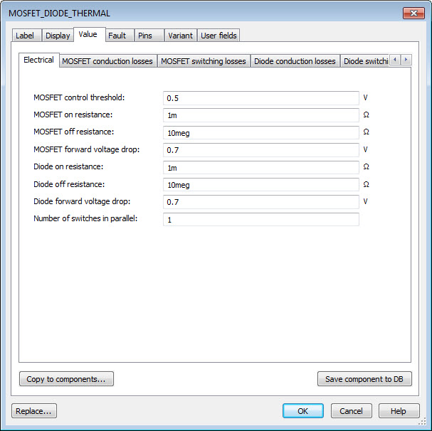
These models include MOSFET_DIODE_THERMAL, IGBT_DIODE_THERMAL, and DIODE_THERMAL. These models are designed to enable you to take the information from the vendor data sheet, enter it in, and have an accurate model of the device performance that includes steady-state temperature, transient thermal temperature, switching and conduction losses, etc.
Here are the basic steps to model the EPC 2015 Enhancement Mode Power Transistor.
1. Download and install the latest version of the Multisim and LabVIEW development toolchains (instructions). These can be installed in evaluation mode and then activated.
2. You may want to start with an existing co-simulation example from the GPIC Reference Design and Training Workshop such as the Half-Bridge Inverter Control example in the GPIC Reference Design Project named "[TestBench] Half-Bridge IGBT Control - Sine-Triangle PWM.vi" with corresponding Multisim circuit "Half-Bridge IGBT Inverter.ms13".
3. Replace the IGBT_DIODE_THERMAL models with the MOSFET_DIODE_THERMAL models from the Multisim component library. You can find this in the Master Database under Power>Switches.
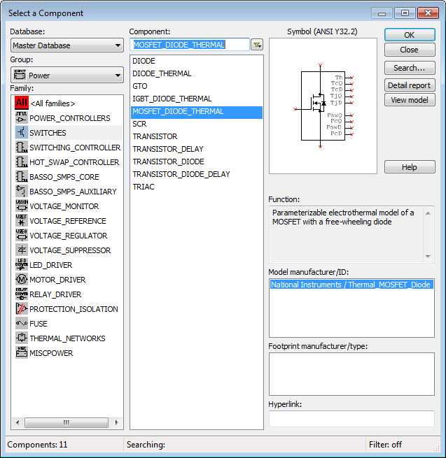
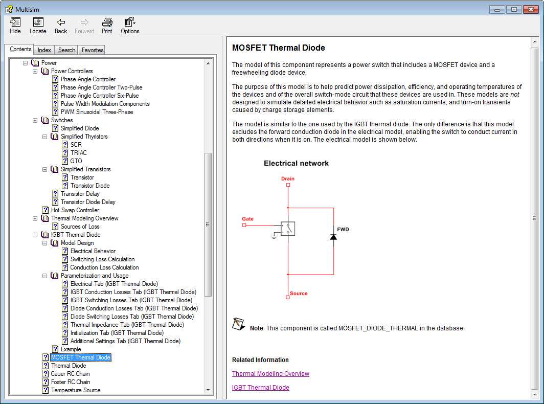
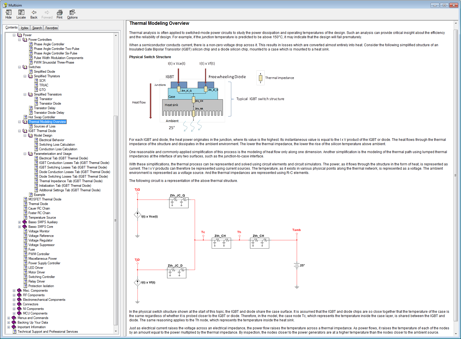
4. Right click on the MOSFET Thermal Diode model and go to properties. Then click the Help button to familiarize yourself with the Multisim device model. You'll actually find most of the documentation in the IGBT_THERMAL_DIODE help. The reason is that the only difference between the IGBT and MOSFET models is that the MOSFET model excludes the forward conduction diode in the electrical model, enabling the switch to conduct current in both directions when it is on. Familiarize yourself. Here is a summary document. In fact, you may want to browse the contents of the entire Multisim Power library online help (shown below).
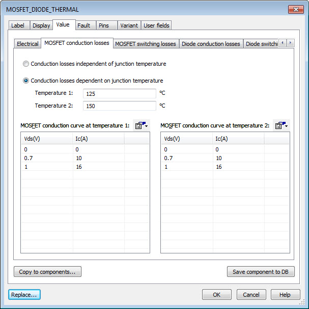
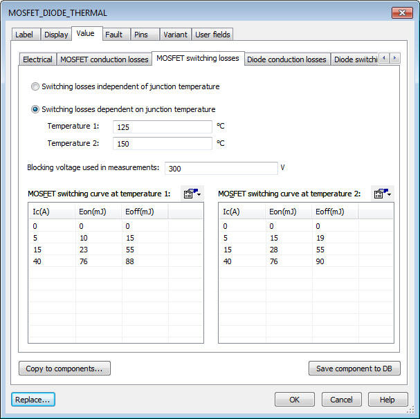
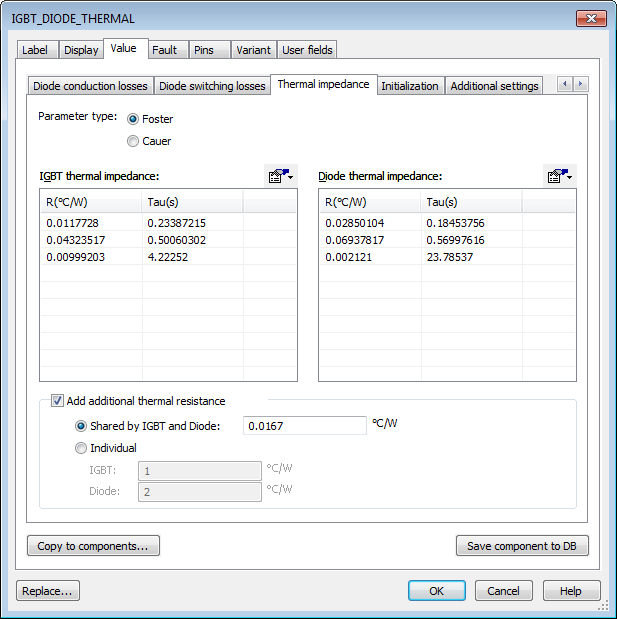
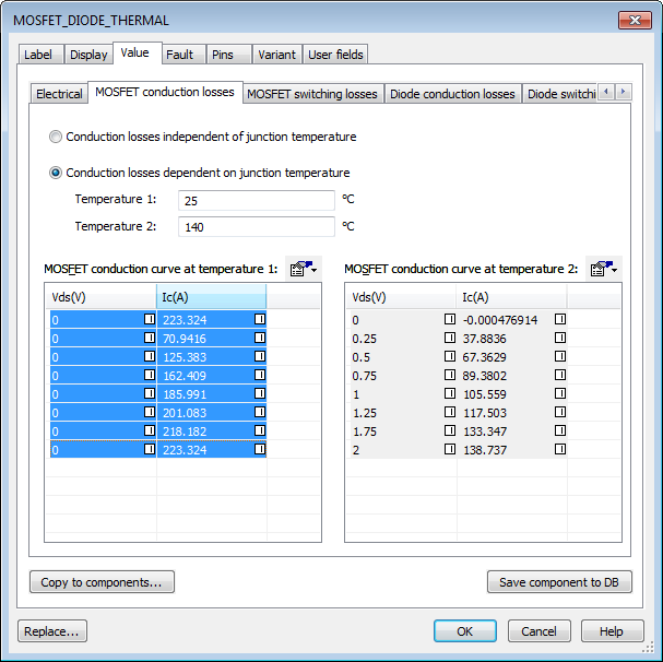
5. Type in the parameters from the EPC2015 datasheet into the MOSFET_DIODE_THERMAL model. This includes basic Electrical, conduction losses, switching losses and thermal impedance from junction to case. Note that you can simulate self-heating effects and thermal runaway if you include the losses at two different temperatures.

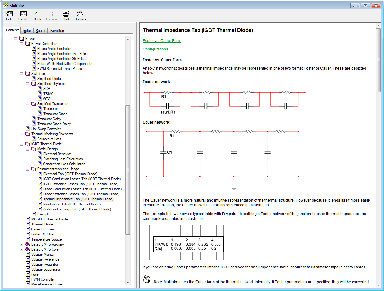
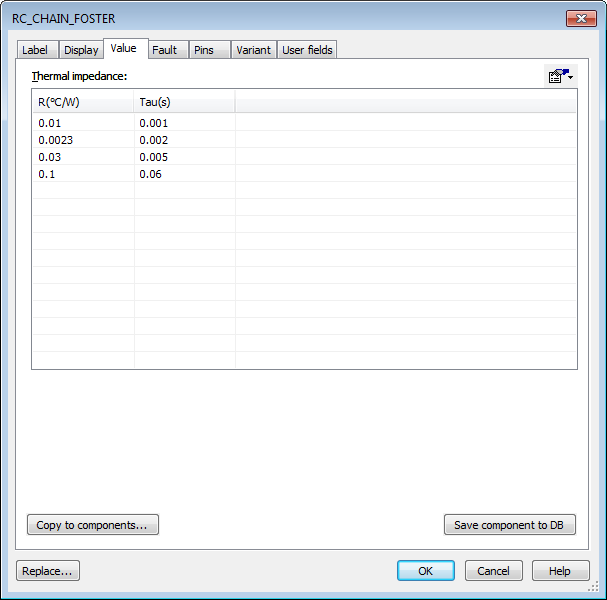
6. Based on this document, EPC provides the thermal impedance for the part from junction to case as a Foster network of thermal resistances and capacitances. Simply type those values into the Thermal impedance tab.
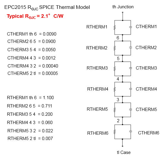

Note: Multisim allows a 5th order Foster network as the maximum, so in this case I combined the 4th and 5th stage from the EPC datasheet. (There are tools that could help you calculate equivalent Foster/Cauer circuits.) The most important thing is that the sum of the resistance values is the same as the sum of the resistances on the datasheet- resulting in the same DC equivalent thermal impedance.
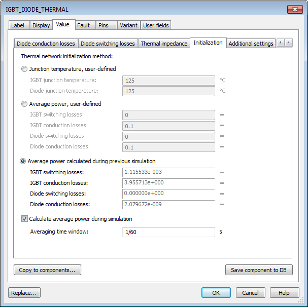
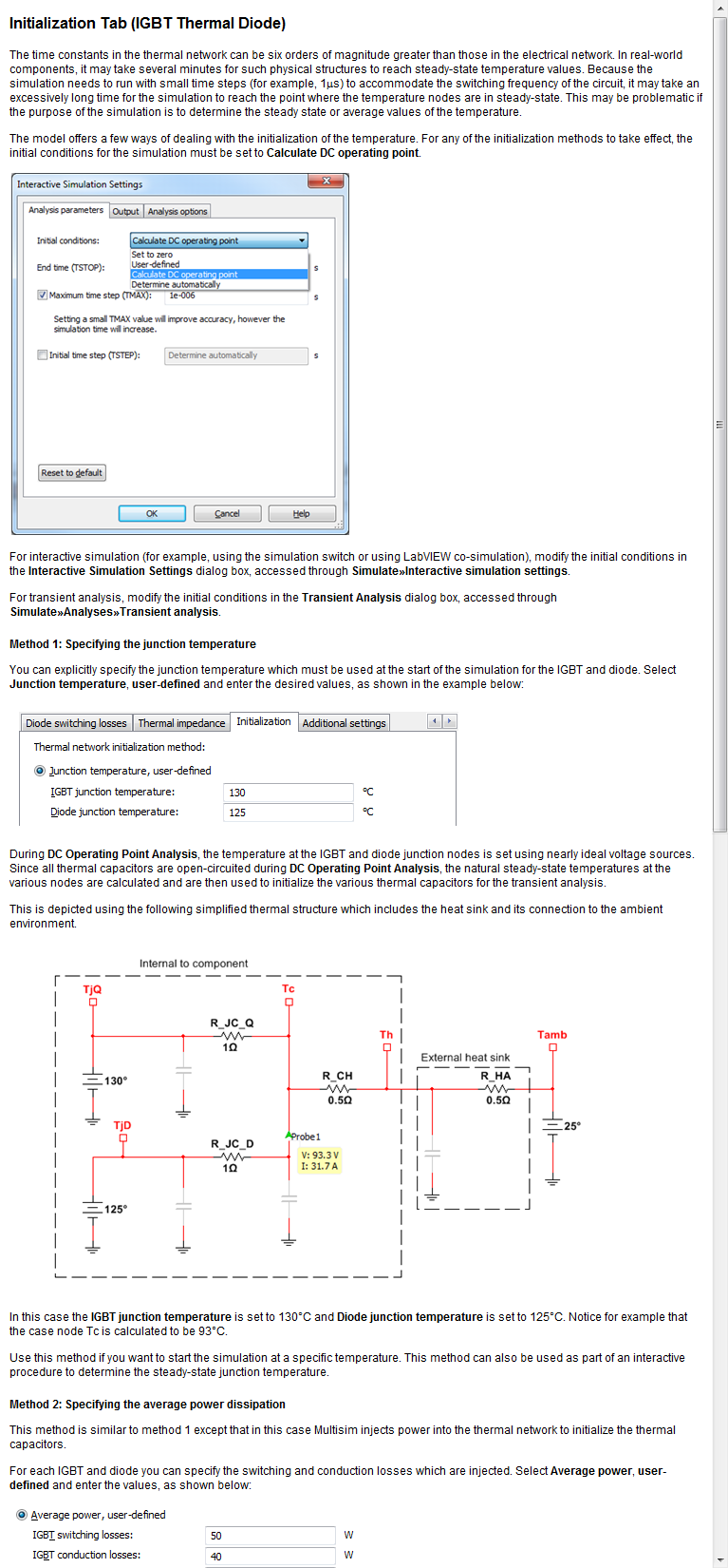
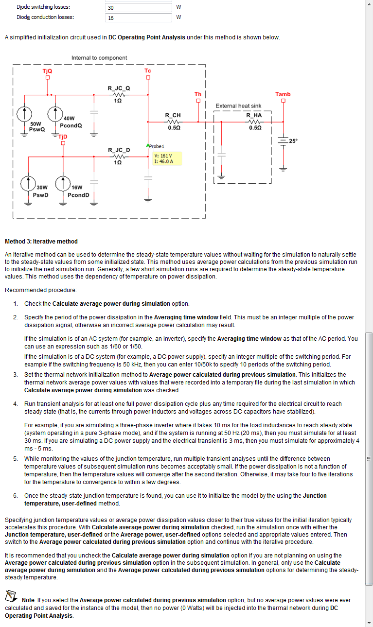
7. Finally, configure the initialization of the thermal model. This is one of the features I'm most proud of. As you know, the thermal network is much much much slower than the switched mode power electrical behavior. So, to eliminate the need to run the simulation for hours just to find out the steady-state temperature, we developed a way to automatically initialize the thermal network to the steady state temperatures. We do this by storing the loss information in each transistor from the previous run of the simulation, and using that to determine the DC operating point. Run the simulation once, and then when you start it the second time the temperature starts at the steady state and you will see the transient thermal behavior oscilating around the steady state value. This works for any switching topology (NPC, matrix, etc.) because we store the loss information in each transistor individually. Here is a screenshot of the documentation for the initialization tab.
8. Enter in the thermal model for your heatsink in Foster or Cauer Network format.
Note: If the heatsink vendor doesn't provide a transient thermal model, you can use a simple resistor component to represent the overall equivalent thermal impedance (C/W). You could also measure the transient thermal response experimentally.
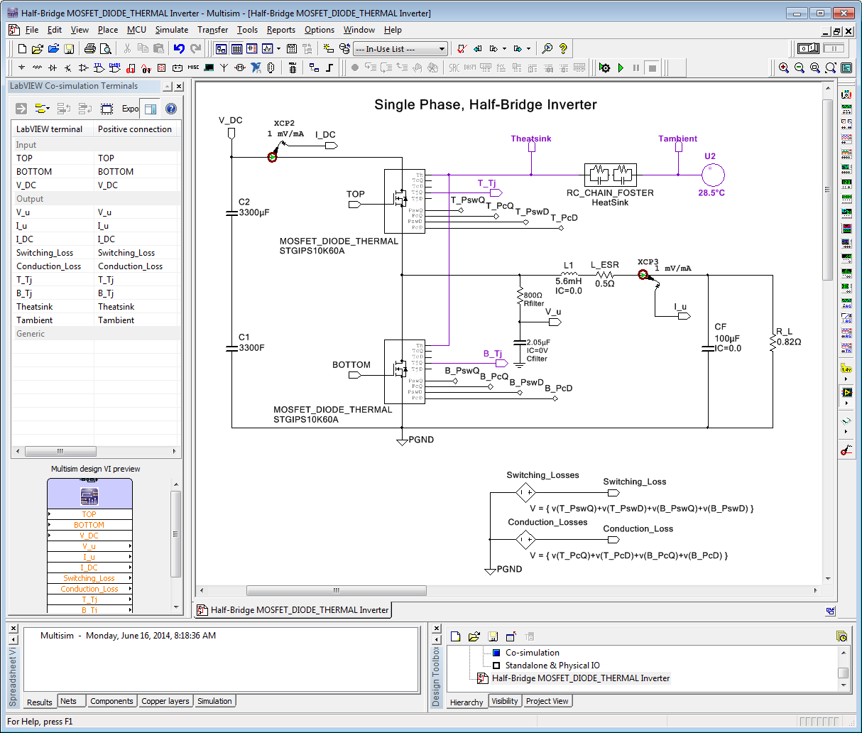
9. Also set the ambient temperature. In this case, it's set to 28.5 degrees C. Your final Multisim simulation model should look something like this.
10. In the LabVIEW co-simulation application, refresh the Multisim co-simulation interface and run the simulation. After it has reached steady state (2-3 cycles at 60 Hz), stop the simulation and restart it. Now the thermal network starts at the correct DC offset temperature for each of the transistors in the circuit.
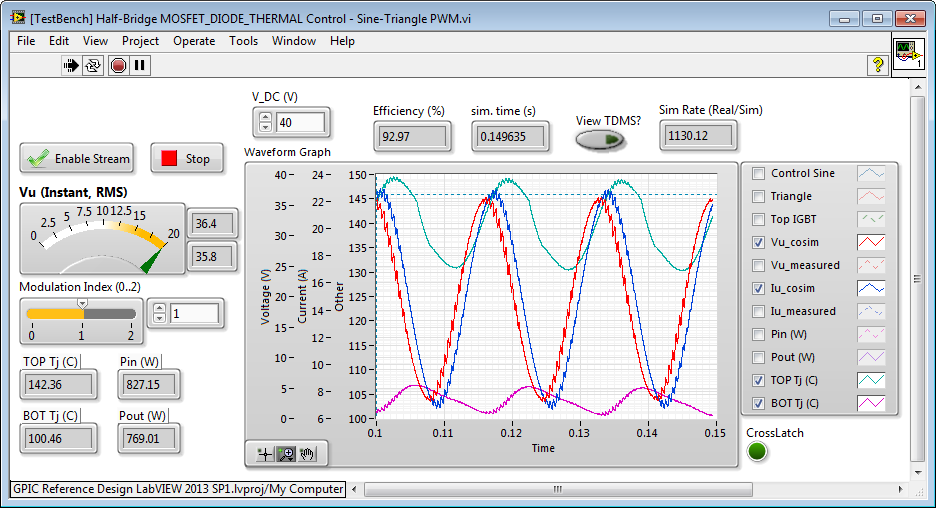
Below you can see the voltage, current and transient thermal oscillations of the upper and lower MOSFET in the half-bridge. In this case we are doing FPGA-based sine-triangle pulse width modulation with a 2 kHz carrier frequency.
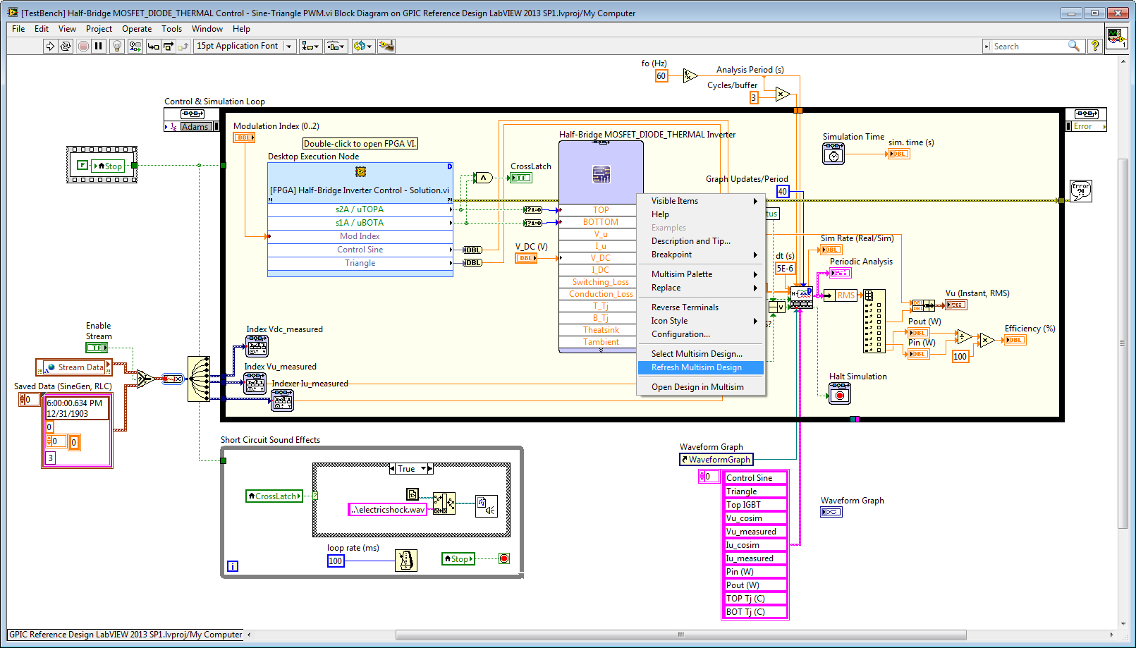
Here is the LabVIEW FPGA control application. Note that the thermal and efficiency/loss calculations are based on the exact control algorithm and PWM logic in your FPGA application. If you were to implement different control schemes like space-vector PWM, you could easily evaluate the effect on the device temperature and energy efficiency.
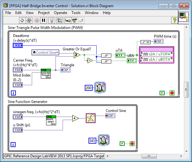
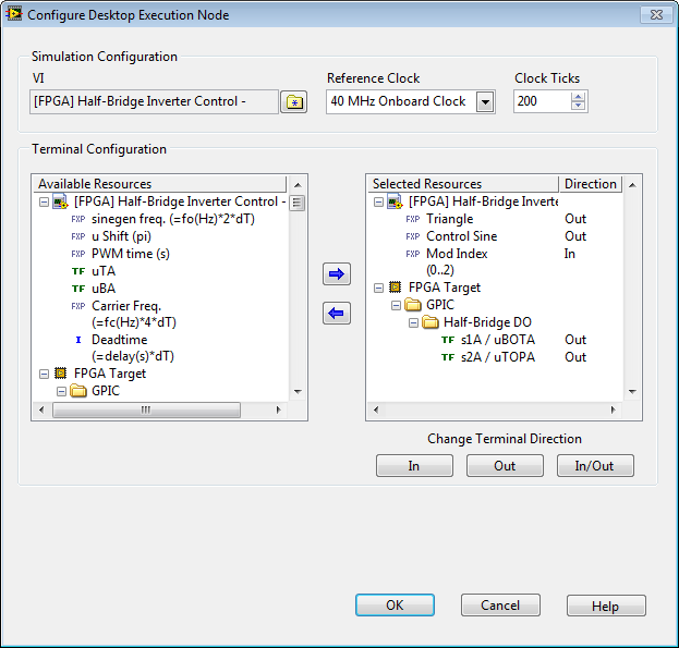
Note: As a rule of thumb, the loop rate of the pulse-width modulation loop in LabVIEW FPGA and the update rate of the FPGA Desktop Execution Node (DEN) in the co-simulation application should be at least 100 times faster than the PWM switching frequency. In this case, the switching frequency is 2 kHz, so we choose 200 ticks (5 microseconds) for the PWM loop and DEN update rate. This determines the time interval between updating the switch states passed to Multisim, so it's important for the accuracy of the circuit simulation. In the co-simulation application, right-click on the DEN to configure it. Note that Clock Ticks is set to 200, which is also the rate of the PWM loop, so the DEN will update the co-simulation application on every iteration of the PWM control loop.
In practice, the PWM logic is typically included in a single-cycle timed loop (SCTL) executing at 40 MHz. In this case, you would set Clock Ticks in the DEN to 1 so the co-simulation application updates (and passes the switch states to Multisim) on every clock tick.
The example code above is attached. Note however, that I didn't enter all the EPC2014 circuit parameters in the MOSFET models, so you will need to do that using the vendor datasheet. Also note that the vendor didn't provide a Foster/Cauer thermal network from the Diode to the Case so I used the same MOSFET thermal network for the Diode.
Note: We are currently working on the advanced transistor model specification for the next version of the FPGA-based motor/power converter hardware-in-the-loop (HIL) real-time simulation toolkit. What features of the Multisim THERMAL models do you need for real-time HIL simulations? Also, what types of SMPS/Power Converter faults do you need to simulate for HIL testing/validation of the embedded control system? Please reply to this thread with your comments. We appreciate the feedback and thoughts.
06-16-2014 11:50 AM
- Mark as New
- Bookmark
- Subscribe
- Mute
- Subscribe to RSS Feed
- Permalink
- Report to a Moderator
I just updated the code to include transistor lifetime (mean time before failure) calculations.
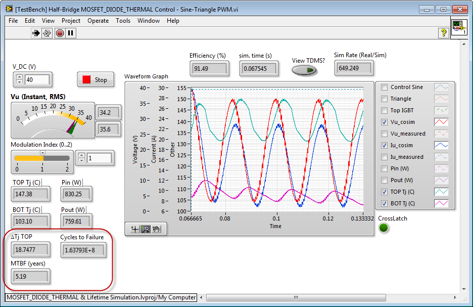
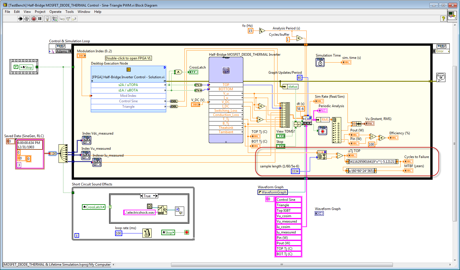
The calculations for the Cycles to Failure is based on an MS Excel curve fit to the vendor datasheet information. In this case, I'm using the datasheet for the Fuji Econodual V Series IGBT modules. These are the same IGBT modules used in the Methode SmartPower Stack.
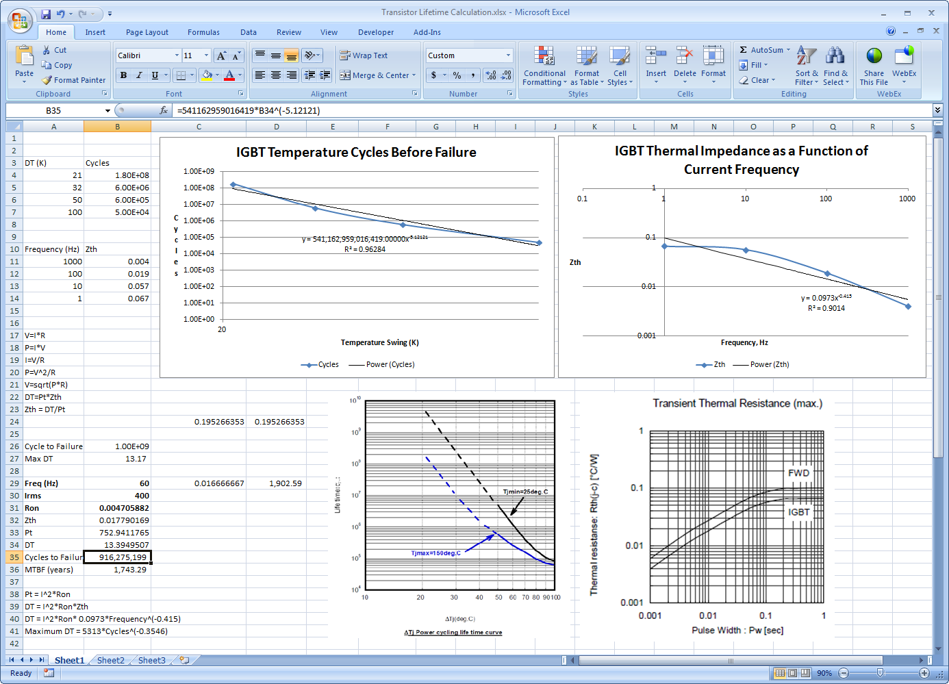
I put 3 data points above into Excel and did a fit. Since it's a log-log relationship, the data fits a power law equation. A simple power law equation models it pretty well.
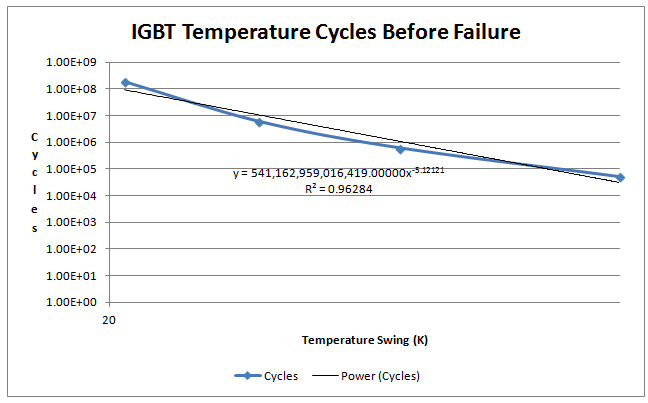
In this case, the curve fit finds.
IGBT Temperature Cycles Before Failure = 541162959016419*DT^(-5.12121)
or
Maximum DT = 755*Cycles^(-0.1953)
So, let's say we need a lifetime of 1 Billion cycles. Then the Maximum DT = 13 degrees C.
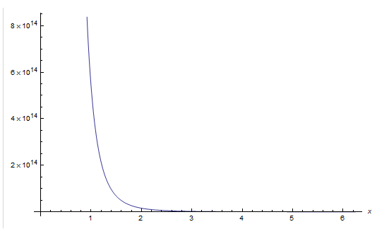
Plotting the curve fit equation for lifetime cycles vs. temperature swing on linear scale below. (Plot by Wolfram Alpha.)
Then we can calculate the mean time before failure in years as follows.
MTBF (years) = (CYCLES_TO_FAILURE)/(fo*60*24*365)
Where fo is the temperature cycling frequency-- in this case 60 Hz.
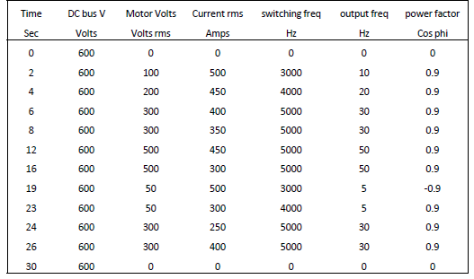
In practice, the actual delta-T temperature cycling depends on the mission profile. This is a repetive sequence used to represent the swing of voltage, current, switching frequency, output frequency and power factor that the converter will experience during daily operation. Here is an example of a mission profile from an excellent presentation on the subject by David Levett of Infineon, "Meeting reliability and lifetime goals in IGBT-based converter designs." This presentation is included in the ZIP file above-- see the References subfolder.
06-19-2014 05:16 PM
- Mark as New
- Bookmark
- Subscribe
- Mute
- Subscribe to RSS Feed
- Permalink
- Report to a Moderator
Thank you for your reply, Brian. One more thing, for the EPC GaN, how to type in the parameters in step 5.
06-19-2014 06:42 PM
- Mark as New
- Bookmark
- Subscribe
- Mute
- Subscribe to RSS Feed
- Permalink
- Report to a Moderator
For the thermal impedance, if PCB board is used for the heat dissipation of GaN rather than peripheral heatsink, should I use the paprameters from junction to board?
06-19-2014 08:09 PM
- Mark as New
- Bookmark
- Subscribe
- Mute
- Subscribe to RSS Feed
- Permalink
- Report to a Moderator
Are you asking how to calculate the values to type in on step 5 based on the datasheet information? If so, that's a really good question. It's a bit confusing so I put together some documentation on it some time ago...
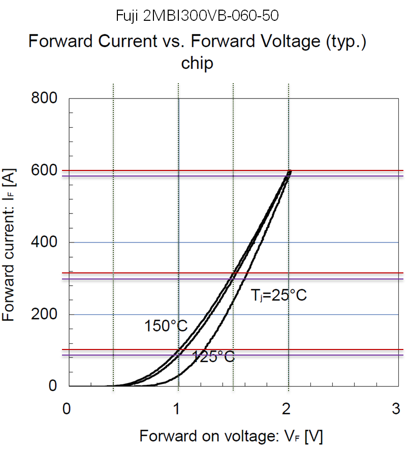
Here is an example for a Fuji 2MBI300VB-060-50 V Series IGBT half-bridge module. The text below each
screenshoot is psuedocode that explains how to calculate the parameters from the datasheet info above.
Electrical Parameters
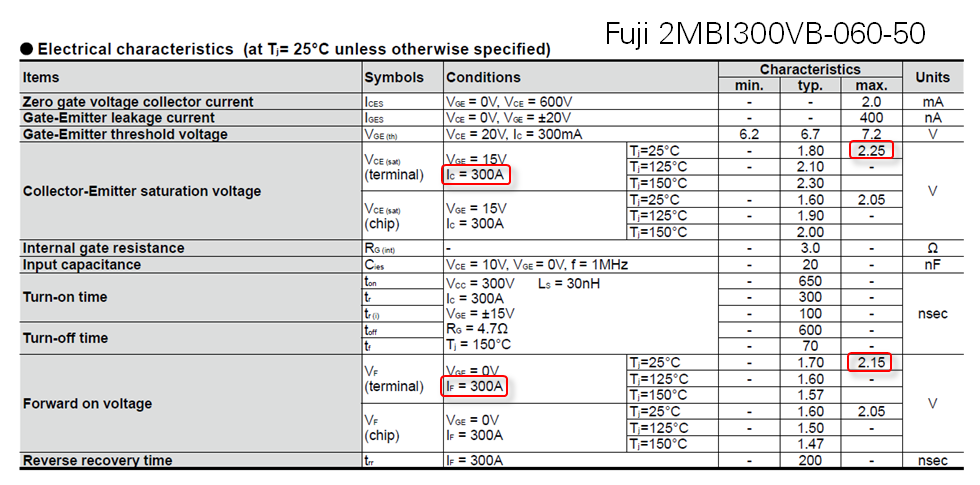
*******ELECTRICAL PARAMETERS*******
** Ohms, IGBT conduction resistance. On the datasheet table, use the max (worst case) Collector-Emitter Saturation Voltage divided by the current I_C.
.param IGBTRon=2.25/300
** Ohms, IGBT blocking resistance. Not typically listed on the datasheet. Use a large value like 1 MOhm.
.param IGBTRoff=1meg
** V, Voltage at which the IGBT begins to conduct on the I_C vs. V_CE datasheet curve. Identify the V_CE at which the device first begins to conduct the highest junction temperature (typically, T_j=>150 C).
.param VceOn=0.7
** Ohms, Diode conduction resistance. On the datasheet table, use the max (worst case) Forward On Voltage divided by the current I_F.
.param DiodeRon=2.15/300
** Ohms, Diode blocking resistance. Not typically listed on the datasheet. Use a large value like 1 MOhm.
.param DiodeRoff=1meg
** V, Voltage at which the Diode begins to conduct on the I_F vs. V_F datasheet curve. Identify the V_F at which the device first begins to conduct the highest junction temperature (typically, T_j=>150 C).
.param DiodeVf=0.6
** Voltage at control pin above which the control is considered High and the IGBT is in the On state.
.param Von={0}
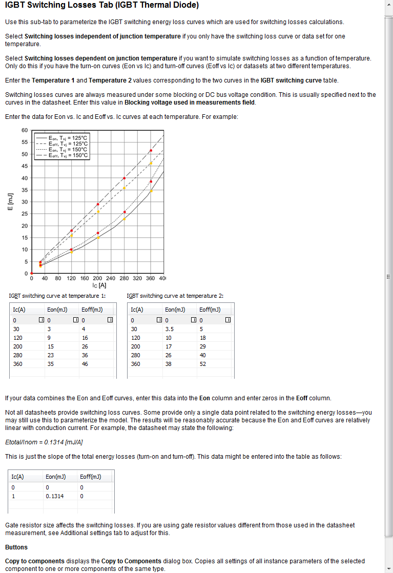
Switching Losses
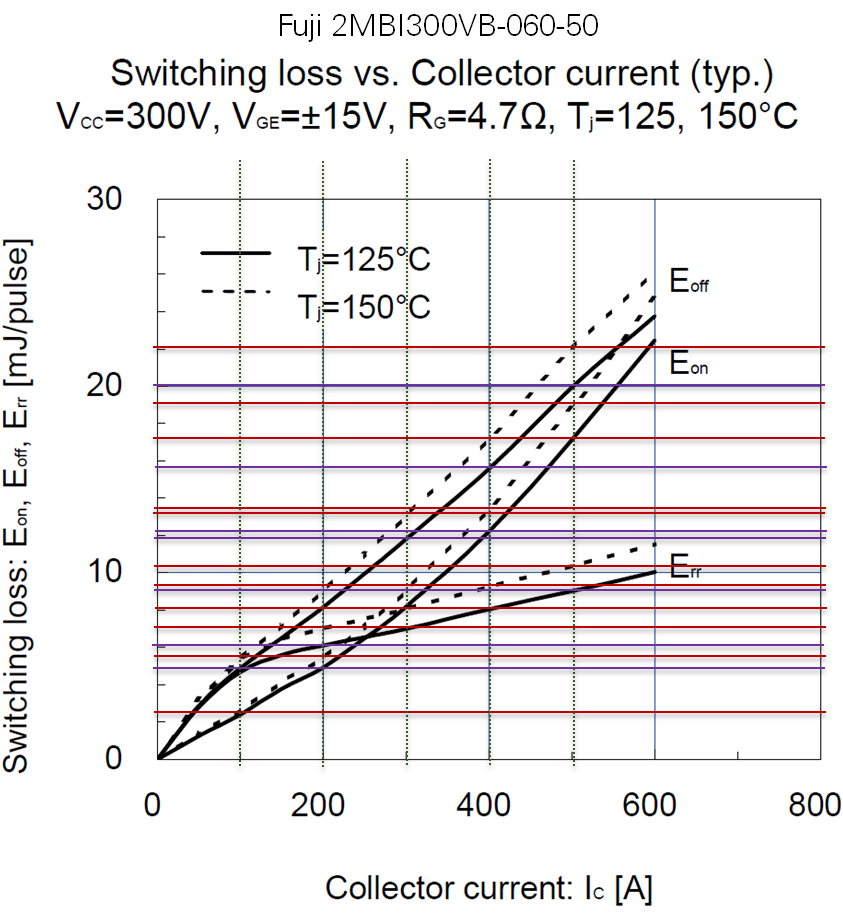
+temp1=125
+temp2=150
******SWITCHING LOSSES******
+ic_array_diode_losses_temp1= [0 100 200 300 400 500]
+err_array_diode_losses_temp1=[0 5 6 7 8 9]
+
+ic_array_igbt_losses_temp1= [0 100 200 300 400 500]
+eon_array_igbt_losses_temp1= [0 2.5 5 8 12 17.2]
+eoff_array_igbt_losses_temp1=[0 5 8 12 15 20]
+
+ic_array_diode_losses_temp2=[0 100 200 300 400 500]
+err_array_diode_losses_temp2=[0 2.5 7.5 8 9 10.2]
+
+ic_array_igbt_losses_temp2=[0 100 200 300 400 500]
+eon_array_igbt_losses_temp2=[0 2.5 5.5 9 14 19]
+eoff_array_igbt_losses_temp2=[0 5.5 9 13 17 22]
Transistor Conduction Losses
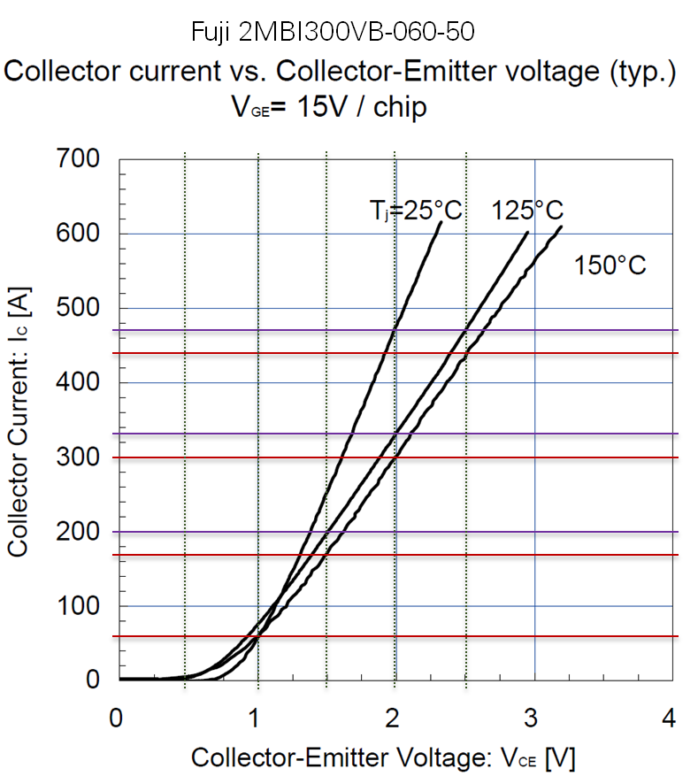
+temp1=125
+temp2=150
******TRANSISTOR CONDUCTION LOSSES******
+vce_array_igbt_forward_temp1 = [0 0.5 1 1.5 2 2.5]
+ic_array_igbt_forward_temp1 = [0 1e-3 60 200 330 470]
+
+vce_array_igbt_forward_temp2 = [0 0.5 1 1.5 2 2.5]
+ic_array_igbt_forward_temp2 = [0 1e-3 60 170 300 440]
Diode Conduction Losses
+temp1=125
+temp2=150
******DIODE CONDUCTION LOSSES******
+vd_array_diode_forward_temp1 = [0 0.5 1 1.5 2]
+ic_array_diode_forward_temp1 = [0 1e-3 85 300 585]
+
+vd_array_diode_forward_temp2 = [0 0.5 1 1.5 2]
+ic_array_diode_forward_temp2 = [0 1e-3 100 320 600]
Transient Thermal Response
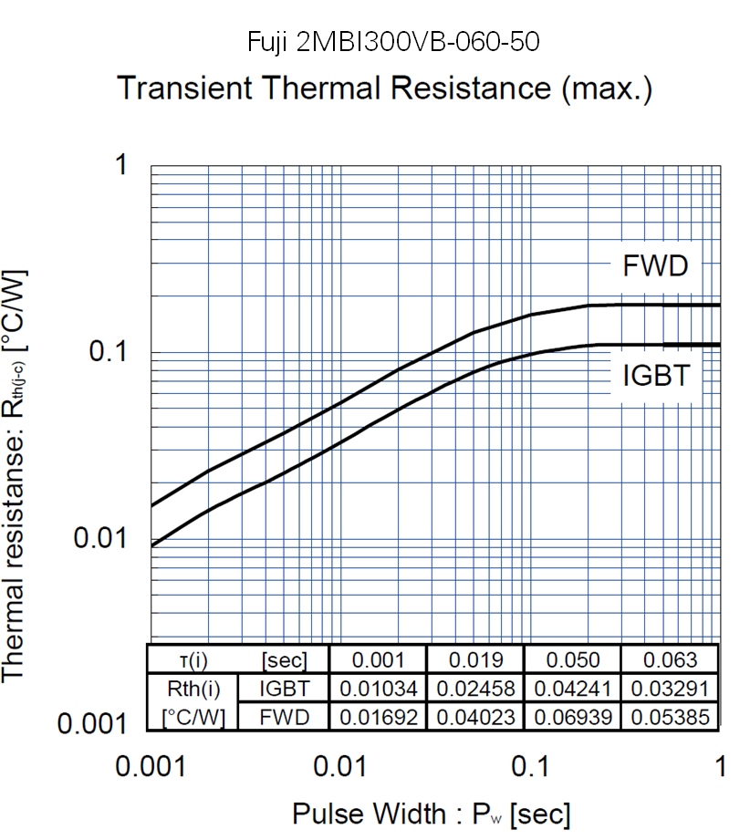
******TRANSIENT THERMAL RESPONSE******
** Note: If the datasheet does not include values for the Foster RC thermal network with equivalent transient thermal resistance, you can use the Semikron Semisel tool to calculate it.
***IGBT Junction-to-Case Equivalent Foster RC thermal network
.param tau1_JC_Q=0.001
.param tau2_JC_Q=0.019
.param tau3_JC_Q=0.05
.param tau4_JC_Q=0.063
.param R1_JC_Q=0.01034
.param R2_JC_Q=0.02458
.param R3_JC_Q=0.04241
.param R4_JC_Q=0.03291
***Diode Junction-to-Case Equivalent Foster RC thermal network
.param tau1_JC_D=0.001
.param tau2_JC_D=0.019
.param tau3_JC_D=0.05
.param tau4_JC_D=0.063
.param R1_JC_D=0.01692
.param R2_JC_D=0.04023
.param R3_JC_D=0.06939
.param R4_JC_D=0.05385
Using the Semikron Semisel Standalone Program to calculate the Zth equivalent Foster RC thermal network
First, values from the transient thermal curves on the datasheet are typed into a spreadsheet.
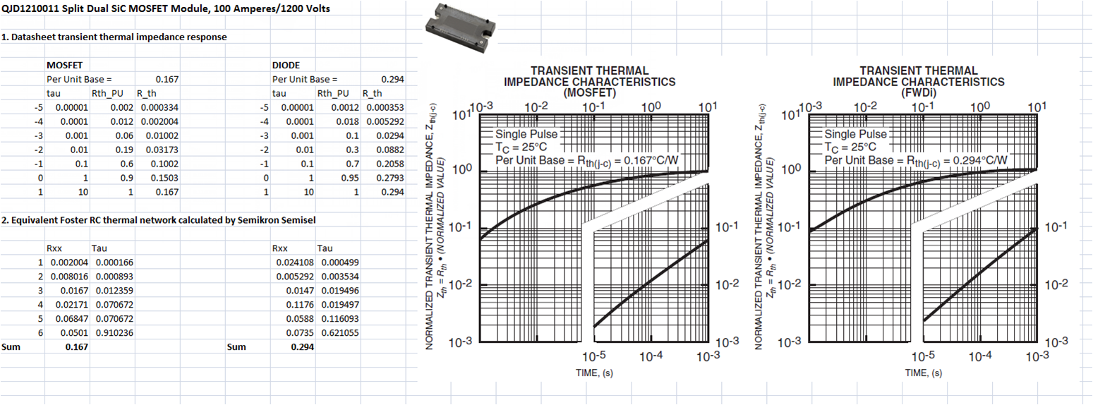
Then Semikron Semisel is used to calculate an equivalent RC thermal network.

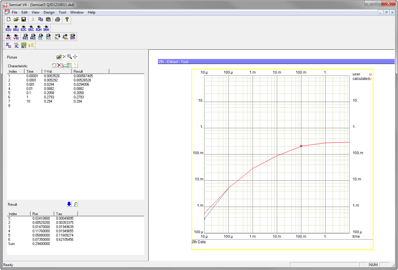
Then the thermal impedance network is typed into the Multisim component values for the IGBT/Mosfet and the Diode.
06-20-2014 01:50 AM
- Mark as New
- Bookmark
- Subscribe
- Mute
- Subscribe to RSS Feed
- Permalink
- Report to a Moderator
Thank you for your explanation. But if you check the datasheet of EPC GaN, you will find that some of the curves are unavailable.
06-20-2014 12:11 PM
- Mark as New
- Bookmark
- Subscribe
- Mute
- Subscribe to RSS Feed
- Permalink
- Report to a Moderator
It looks like provide I-V curves, conduction loss, but I don't see switching loss data for the MOSFET and Diode. You may have to contact the vendor for that information.
In recent years, we've added thousands of power electronics component models to Multisim such as IGBTs, MOSFETs, electric machines and loads. (There are over 26,000 total device models in Multisim.) This includes over 1,500 discrete component models for Infineon components. The Infineon models are provided in three fidelity levels-- simplified (basic) electrical, standard (physics based SPICE) model, and electrothermal model.
In the case of your device of interest, the EPC2015 standard (physics based SPICE) model was added to Multisim last year. This includes modeling of temperature effects on the device transfer characteristics. However, it is not an electrothermal model, which is why I recommended the MOSFET_DIODE_THERMAL model for that purpose. Nonetheless, the SPICE model is still useful to get the I-V curve values in a numeric form. (I'll explain below.)
More info on the EPC device models here:
Design Efficient Fast Switching Power Converters with EPC eGAN FETs
Video: Efficient Fast-Switching Power Converters Design With NI Multisim
Okay, I mentioned that you can use the EPC SPICE model to get the transfer characteristic values needed for the electrothermal model. You may want to start with this tutorial video on the basics of how to get the transfer characteristics for a MOSFET in Multisim such as the Id vs. Vds curves.
NI Multisim: MOSFET transfer characteristics
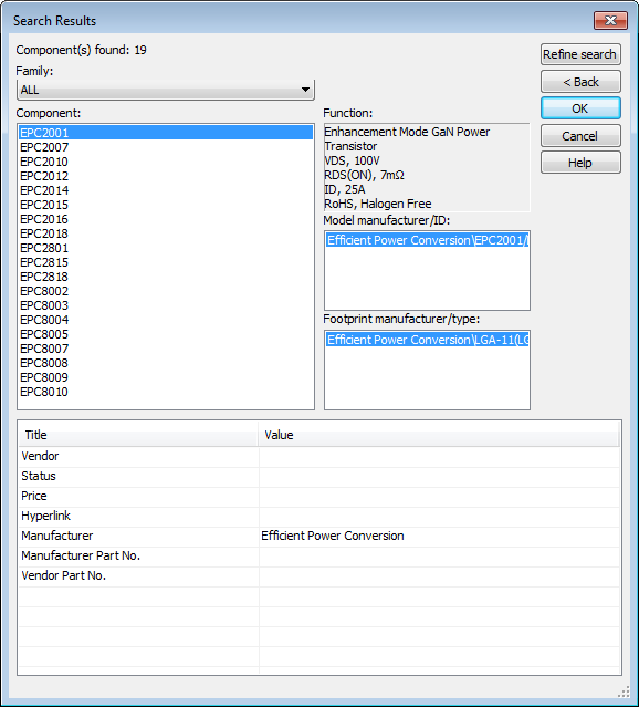
First, to find the Efficient Power Conversion part models, right-click and go to the component library and click search. Then type EPC in the Model ID field and search. You can see there are 19 EPC components in Multisim 2013.
Here's a simulation I put together to do the MOSFET curve tracing. The I-V Analyzer instrument is obviously very helpful for this. Use the cursor to get exact numeric values for drain current (ID) at different values of Vgs, as shown below.
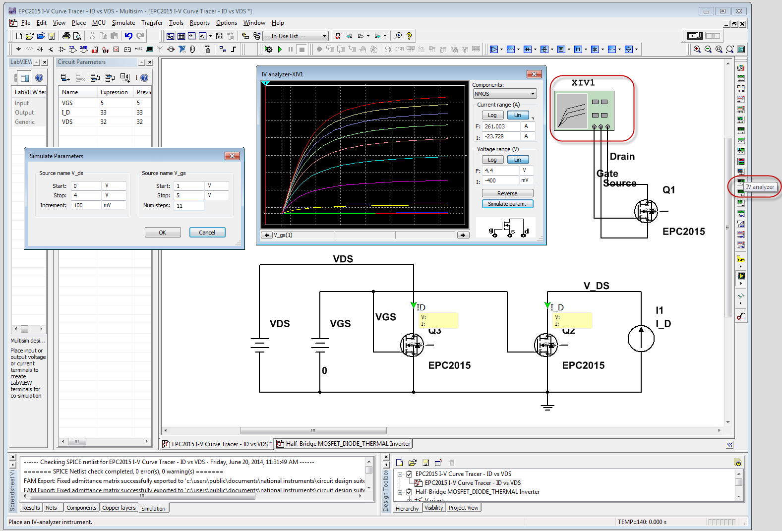
Check that results match the datasheet at 25 C. (The quality of vendor supplied SPICE models varies.)

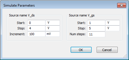
In the simulation above, the I-V Tracer parameters are set to sweep V_ds from 0 to 4 V and V_gs from 1 to 5 V.
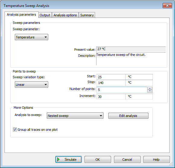
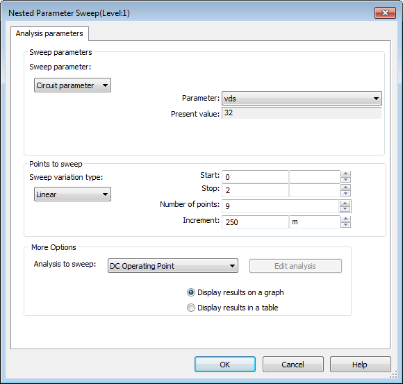
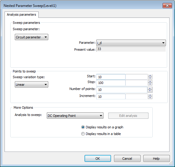
To get the curves needed to represent MOSFET conduction losses versus temperature, use the Temperature Sweep analysis (Simulate>Analyses>Temperature Sweep). If you do a nested sweep, you can get Vgs versus ID and Vgs versus RDSon at different junction temperatures all in one shot, as shown below.

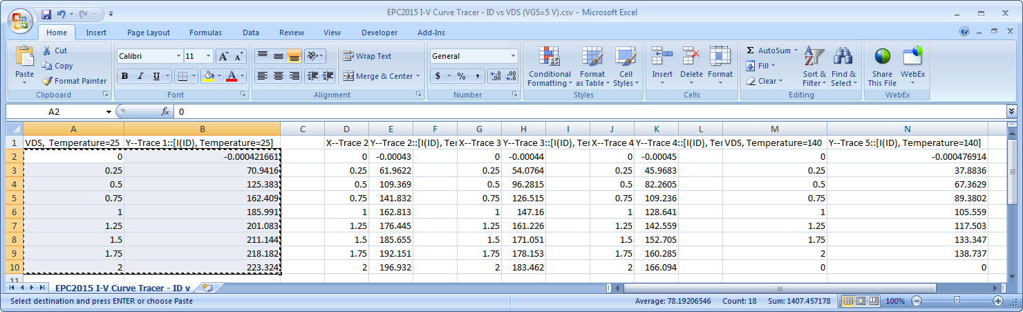
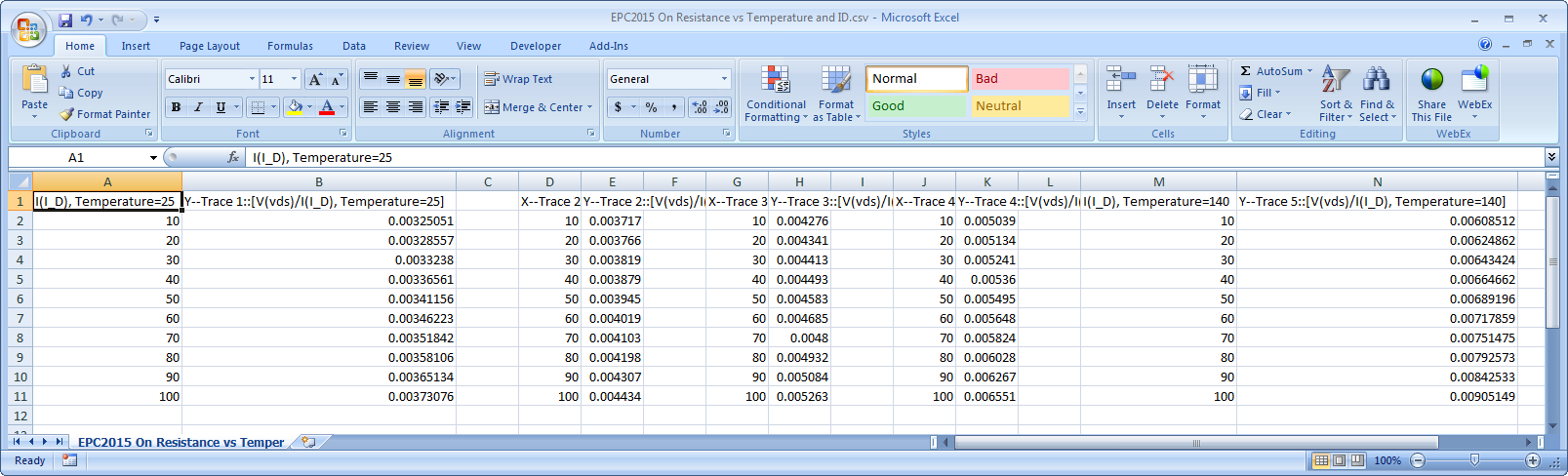
Here is the data showing the temperature dependence of the I-V characteristics. Use the cursors to preview the exact numeric values as shown, and then export the results to a CSV file (from the Grapher, go to File>Save As>CSV). In the sweep below, VGS=5.
.png)
Then I can copy the data from Excel right into the MOSFET_DIODE_THERMAL model.
Or you can do the sweep differently to get the on resistance (RDS(ON)=VDS/ID) at different drain currents (ID) and temperatures. In this case, I use a current source input to the MOSFET and control VGS.
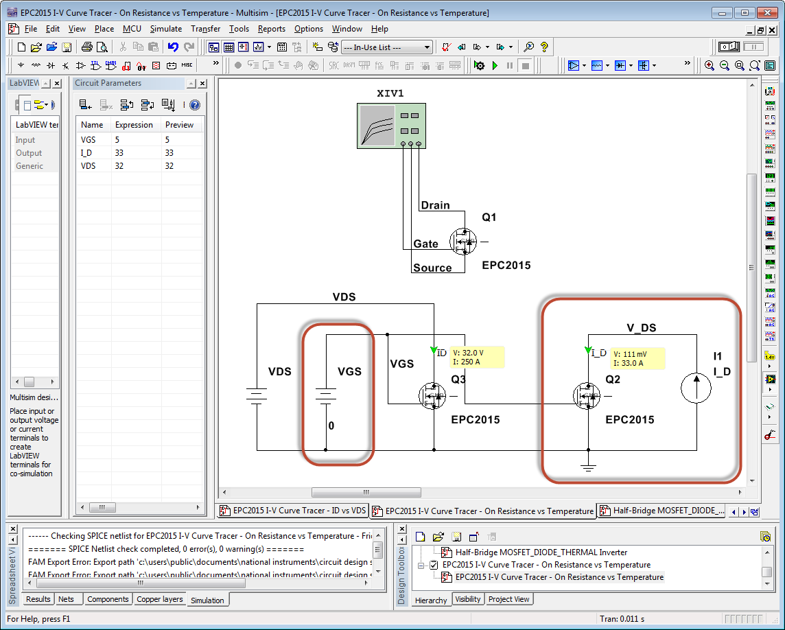
We sweep I_D from 10 to 100 Amps and chart the on resistance (RDS(ON)=VDS/ID) at different temperatures.

Note from the cursor table that Rds = 3.3 mOhms at ID = 33 Amps and Temperature = 25 A. This matches the datasheet value for the part.

Of course, you can also save a CSV file for this data.
I've updated the ZIP file that's attached above in this thread with these simulations (TRANSISTOR THERMAL & Lifetime Simulation.zip).
06-20-2014 01:35 PM
- Mark as New
- Bookmark
- Subscribe
- Mute
- Subscribe to RSS Feed
- Permalink
- Report to a Moderator
I really apprcciate your helpful information. One more thing, the switching loss data are only included in the datasheet of IGBT. For MOSFETs and GaN, how to get that? I asked EPC about that. But they said they don't have that information now. I am not sure whether other MOSFETs producers have that data. Usually, for me, the switching losses are calculated according to the operation of the circuit (for example switching frequency, soft switching or hard switching, etc.). So what does that curve mean?
06-20-2014 02:52 PM
- Mark as New
- Bookmark
- Subscribe
- Mute
- Subscribe to RSS Feed
- Permalink
- Report to a Moderator
You bet. This is a really important topic-- thermals and energy efficiency are top issues in every power electronics design.
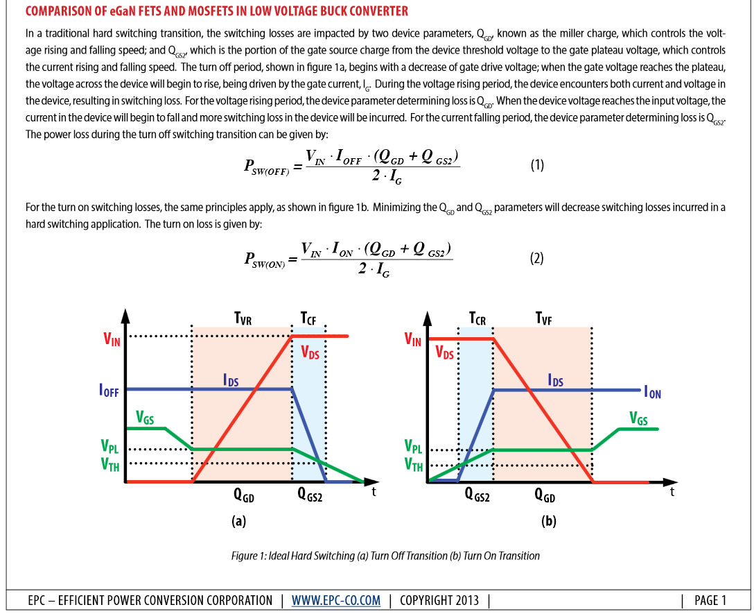
See this application note from EPC which explains how to use the device parameters on the datasheet to calculate the turn on and turn off losses (also browse their other app notes). Using these equation, I believe you can make a table of switching loss versus drain current, and then enter that into the Multisim MOSFET_DIODE_THERMAL model.
Impact of Parasitics on Performance
You might also find this article helpful.
Calculating power loss in switching MOSFETs
