- Subscribe to RSS Feed
- Mark Topic as New
- Mark Topic as Read
- Float this Topic for Current User
- Bookmark
- Subscribe
- Mute
- Printer Friendly Page
Engine Simulation Toolkit Feedback
09-25-2014 04:30 PM
- Mark as New
- Bookmark
- Subscribe
- Mute
- Subscribe to RSS Feed
- Permalink
- Report to a Moderator
Stephen,
I'm testing the knock simulation and it appears the probability setting isn't working. If I set it to 100% I will see the knock on everying engine cycle as expected. However, if I set the probability to anything less than 100% I never see the knock occur. For example the knock never occurs when I have it set to 99%. I'm using default settings for everything else. Let me know if you want me to test anything on my end.
09-26-2014 11:50 AM
- Mark as New
- Bookmark
- Subscribe
- Mute
- Subscribe to RSS Feed
- Permalink
- Report to a Moderator
Hey Todd,
I found an issue in initialization that caused this problem. Thanks for reporting it. I've posted a new version of the custom device, 1.2.7, that resolves it.
10-06-2014 12:15 PM
- Mark as New
- Bookmark
- Subscribe
- Mute
- Subscribe to RSS Feed
- Permalink
- Report to a Moderator
Hi Stephen,
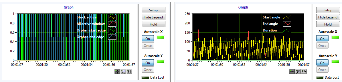
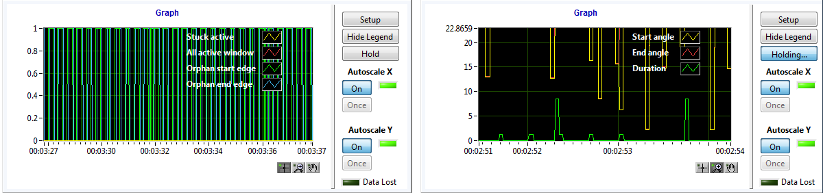
I am trying to use the ECU Event Timing Capture function to obtain the duration of injection trigger signal. However, the duration cannot be accurately calculated, lots of pulses got missing and there are periodic orphan end edges as shown in the attached images.
The input signal is avtive low(normally 1V and falling edge to 0V) and lasts for 1.25ms per approximately 70ms.
For event measurement configuration, the window is set as 0 to 719.978 degreeds and polarity is avtive low. I tried several tests with different Target Rate and DAQ DIO Rate in 'Controller' configuration(up to 5000Hz for both) but got similar results.
Did I have anything wrong in configuration?
Thanks.
Jian
10-06-2014 12:23 PM
- Mark as New
- Bookmark
- Subscribe
- Mute
- Subscribe to RSS Feed
- Permalink
- Report to a Moderator
Hi Jian,
What hardware are you using? 1V is a very low 'high' voltage.
What do you mean by "1.25ms per approximately 70ms"
Can you use an oscilloscope to capture the pulse? There might be noise causing false triggering.
Take care
10-06-2014 12:49 PM
- Mark as New
- Bookmark
- Subscribe
- Mute
- Subscribe to RSS Feed
- Permalink
- Report to a Moderator
Thanks, Stephen!
I forgot to configure the threshold for logic high and low. Sorry for the confustion, 1.25ms is the duration and 70ms is the period.
Jian
10-06-2014 12:56 PM
- Mark as New
- Bookmark
- Subscribe
- Mute
- Subscribe to RSS Feed
- Permalink
- Report to a Moderator
Hi Jian,
Do you mean it is fixed now? Can you elaborate on what the problem was?
Thank you
10-06-2014 01:58 PM
- Mark as New
- Bookmark
- Subscribe
- Mute
- Subscribe to RSS Feed
- Permalink
- Report to a Moderator
In my system, the 4 NI 9401 modules are connected to a ditigal IO board which allows me to modify the threshold to determine 'high' by placing a jumer to different locations. After I changed the reference voltage and threshold, I got correct duration calculation compared to my signal generator.
Is there a way to configure the threshold in software?
Thanks.
10-06-2014 02:12 PM
- Mark as New
- Bookmark
- Subscribe
- Mute
- Subscribe to RSS Feed
- Permalink
- Report to a Moderator
Jian,
Currently there is not a way to configure these settings in software. We are working on a SPI interface to handle this in future DET systems though.
Thanks,
Todd
10-06-2014 04:23 PM
- Mark as New
- Bookmark
- Subscribe
- Mute
- Subscribe to RSS Feed
- Permalink
- Report to a Moderator
Hi Stephen,
I am trying to generate a VR sensor signal through Digital Pattern Generation. I can get correct signal waveform with specified missing teeth. The problem is that I cannot control the simulated VR sensor signal amplitude(only 1.1V compared to 11V reference voltage).
I tested the same digital pin through LabVIEW scan interface and the amplitude was same as reference voltage.
Are there configurations to be set to specify the generated digital pattern amplitude?
Thanks.
Jian
10-07-2014 12:52 PM
- Mark as New
- Bookmark
- Subscribe
- Mute
- Subscribe to RSS Feed
- Permalink
- Report to a Moderator
Hi Stephen,
I think I found the cause. In the FPGA vi, the digital module was configured as input. I will correct the configuration, compile it and see if that fixes the issue. Will let you know the result.
Jian
