- Subscribe to RSS Feed
- Mark Topic as New
- Mark Topic as Read
- Float this Topic for Current User
- Bookmark
- Subscribe
- Mute
- Printer Friendly Page
boost converter simulation
09-23-2015 06:37 PM
- Mark as New
- Bookmark
- Subscribe
- Mute
- Subscribe to RSS Feed
- Permalink
- Report to a Moderator
i am try to do simulation for boost circuit ,but my simulation is not working , the output should be 400 v but in the simulation it is about 150v and also it is going up and down , so can someone help me what i did wrong?
09-24-2015 05:50 PM
- Mark as New
- Bookmark
- Subscribe
- Mute
- Subscribe to RSS Feed
- Permalink
- Report to a Moderator
Hello,
It is hard to tell with just a picture. Uploading the actual file will be more helpful.
National Instruments
09-27-2015 01:50 PM
- Mark as New
- Bookmark
- Subscribe
- Mute
- Subscribe to RSS Feed
- Permalink
- Report to a Moderator
This is different circuit(PFC) but it has the same problem
so can you please help me what is the problem(output is not right , input current is not sinusoidal)
09-27-2015 10:04 PM
- Mark as New
- Bookmark
- Subscribe
- Mute
- Subscribe to RSS Feed
- Permalink
- Report to a Moderator
Can you please check in PFC2 why i do not get 400v out
09-28-2015 07:23 PM - edited 09-28-2015 07:24 PM
- Mark as New
- Bookmark
- Subscribe
- Mute
- Subscribe to RSS Feed
- Permalink
- Report to a Moderator
I didn't really check the second one but I played around with pfc.ms12.
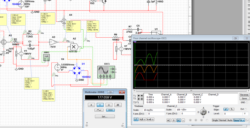
I started placing probes in all the area where you were measuring the output with the multimeter and the voltages seem right after the circuit "stabilizes" (I did notice the AC supply output was not behaving AC-like). Then, I placed a 4 channel oscilloscope and got this.
Does the initial output look similar to what you expect?
What surprised me was that after that, the "stable" circuit was just not really updating any longer, so the simulation would keep running but the values would just not change. I am not sure at this point if this is actually expected or not, but I noticed that if you remove the top part from the circuit it runs indefinitely with a "better behavior".
I say "better behavior" because I really don't know if this is what you are trying to get, but it runs without halting. Now, even at this point the output is not near what you are expecting, so I am wondering if the circuit should actually reach 400V. Can you verify this? Maybe there are a couple things to change to achieve that.
Also, since I know you need the part I deleted, maybe you can use a similar approach in different pars of the circuit to try to identify at which point it starts freezing. If you are able to identify when that happens I can try to research what is going on (the part I deleted was just a "lucky guess", but I don't have any circuit design background so I can only really help you if you are able to narrow down the issue).
I did notice the second file does not freeze, but I did not ran more tests on it so I am not sure if the problem is related to this.
I attached the pictures for better detail.
Regards,
National Instruments


