- Subscribe to RSS Feed
- Mark Topic as New
- Mark Topic as Read
- Float this Topic for Current User
- Bookmark
- Subscribe
- Mute
- Printer Friendly Page
Inconsistency between oscilloscope and LabVIEW readings
05-16-2008 05:47 AM
- Mark as New
- Bookmark
- Subscribe
- Mute
- Subscribe to RSS Feed
- Permalink
- Report to a Moderator
05-19-2008 08:07 AM
- Mark as New
- Bookmark
- Subscribe
- Mute
- Subscribe to RSS Feed
- Permalink
- Report to a Moderator
Hello Hello Imperial-Aero!!
It sounds like you are carrying out a very exciting acoustical experiment. Furthermore, the problems you are currently enduring are interesting to say the least. I for one have not encountered them before.
Thanks for the detailed explanation of your issue. Unfortunately, I do have a couple more questions for you. Firstly, are you capable of turning down the frequency of the generated sound wave while the experiment is running? If so, can you see the difference between MP1 and MP8 extend gradually as the frequency (and response) decreases or is it a sudden jump?
Secondly, could you change the order in which the MICs are plugged into the DAQ card. Does the response pattern remain consistent with the MIC number (i.e. still an unexpected difference between MP1 and MP8) or is it dependant on the DAQ card’s channel number. If the later is the case, we could possibly narrow the cause of the problems down to the PCI-6229’s multiplexer.
Please let me know if you have any more news.
Many thanks for your time and patience,
Senior Marketing Engineer, National Instruments
Connect on LinkedIn: https://www.linkedin.com/in/richard-roberts-4176a27b/
05-19-2008 09:21 AM
- Mark as New
- Bookmark
- Subscribe
- Mute
- Subscribe to RSS Feed
- Permalink
- Report to a Moderator
Thank you for the reply Rich.
Unfortunatenly, the way I've setup up my VI it does not allow changing the frequency. The only thing I can say is that this inconsistency was observed only for low frequencies, in which the response of the system is small. For large amplitude signals the results obtained from LabVIEW agrees with that from the oscilloscope.
I observed something very interesting when I change the connections of the microphones onto my DAQ board. Earlier I've connected them on to the DAQ board in the order they were mounted on the tube, therefore I was expecting them to have gradual changes in the readings. Now I switched the connections to ai6 and ai7 (i.e. MP8 was connected to ai6 and MP7 was connected to ai7). I have attached the waveform (test1.png). Earlier MP8 (connceted to ai7) had the lowest reading but now it seems that MP7(connected to ai7) had the lowest reading. This shows that the readings are dependant on the DAQ channel.
I also completely randomised my signal connections to the DAQ board and observed something even stranger. The attached picture (test2.png) shows the results. The waveforms seem to be completely random. I have used this DAQ board for other tests and did get good results (even for very low amplitudes). The problem with this particular test is that the signals I'm sending to the loudspeakers are a bit unusual as shown on the pic on the first post (I'm trying to spin waves inside the tube), so even though it is difficult to predict what the response is supposed to look like, measured signals from LabVIEW should agree well with the observations from the oscilloscope if the DAQ system is working fine. I guess I'm not looking for a fix, but rather an explanation to what is happening.
Cheers.
05-21-2008
04:27 AM
- last edited on
07-23-2025
11:27 AM
by
![]() Content Cleaner
Content Cleaner
- Mark as New
- Bookmark
- Subscribe
- Mute
- Subscribe to RSS Feed
- Permalink
- Report to a Moderator
Dear Imperial Aero,
OK, you will have to bare with this reply, because I have a rather meandering answer for you. Depending on your responses to the following questions, I expect the issue lies not with LabView (or any of the NI software), but with your PCI-6229 DAQ hardware. The card does not provide true simultaneous data acquisition. The card uses a multiplexer to cycle the analogue input channels through a single ADC and instrument amplifier. Therefore there is a finite amount of time between the data acquired by each of the channels – and, moreover, because the multiplexer cycles through each channel in incremental order, the time difference between the data point of MP1 (at ai0) and MP8 (at ai7) will be most significant.
But here are a few suggestions and questions for you.
1. When you are measuring higher frequency signals you said that you receive a higher amplitude response from the microphones. If this is the case what is the voltage produced? If it is significantly higher than the low-frequency/low-amplitude response, you should be using a smaller input voltage range for the lower frequency signals. The graph that you posted here shows that the response from the microphones is less than 60mV at 100Hz. Therefore the input voltage range for the PCI-6229 should be set to its smallest value – which I believe is +/-200mV.
2. What is the sampling rate you are using?
3. Are you using the same input range for each of the microphone input channels?
4. What is the grounding setup of the signal source (i.e. the microphone)? I believe you have 32 analogue inputs available to you, so perhaps you should consider using differential amplification if applicable (will require 2 inputs per channel). If you need any more information concerning this, please have a look at the following article.
I sincerely hope this has been of some use to you. I apologise for the slightly convoluted response, but I thought it might be beneficial if I shared all my thoughts with you.
Thanks for your time,
Richard
Senior Marketing Engineer, National Instruments
Connect on LinkedIn: https://www.linkedin.com/in/richard-roberts-4176a27b/
05-21-2008 06:23 AM
- Mark as New
- Bookmark
- Subscribe
- Mute
- Subscribe to RSS Feed
- Permalink
- Report to a Moderator
Thank you for the reply Rich.
Yes you're answers were helpful. I did think that it could be the way my card was reading the signals, especially between ai7 and ai0 it goes through ai8 and ai15 as well.
Here are some answers that I've obtained.
1. The voltage reading at peak-to-peak is around 0.45V. I've attached a picture of the input (loudspeaker forcing) and output (microphone reponse) graph. This is ideally what I expect to obtain from the system (i.e. input is same as output). But this only occurs at 290Hz (it's a property of the system) and at this frequency it agrees with the oscilloscope readings. I'm not entirely sure what you meant by changing the input voltage to the DAQ. I'm using a BNC-2090A terminal block for the connections and I can see a +5V light on. Is this what the input is? If I were to change the input how would I do it?
2. I'm using two different sampling rates for both the input and output from the DAQ system. For the loudspeaker forcing (output from DAQ) I sample it at 15000 Hz and I have four analog output channels. For the input signals (both from the microphones and I also read back the signals sent to the loudspeakers after they are amplified by a power amplifier) the sampling rate is 5000Hz. Also, with regards to changing the input, the loudspeaker input signals always have the same voltage regardless of the response since that's what I am forcing. So if I were to change the input voltage of the DAQ to capture the small amplitude signals, will that work since my loudspeaker voltages will still be the same amplitude as for high frequency forcing.
3. The microphones I'm using are identical and simple tie-clip ones that comes with 1 jack. They have identical DC batteries of 1.5V. (I didn't quite understand what you meant by input range).
4. I did think of obtaining differential inputs. But then I'd have to cut my microphone cables and I didn't want to do it since they might be needed for further experiments.
I know some of the stuff I explained might be too technical and specific to my project. But hopefully you can get an idea of my problem. Like I said earlier, if I could get a reason for why it's not working for low amplitudes then it'd be excellent.
05-21-2008 07:59 AM - edited 05-21-2008 08:01 AM
- Mark as New
- Bookmark
- Subscribe
- Mute
- Subscribe to RSS Feed
- Permalink
- Report to a Moderator
Dear Imperial Areo,
Thanks for the further details. Before we try to proceed any further, I thought I would offer some more information on defining the analogue input range of your card.
I am not sure how you are currently setting up your channels/tasks, but in this example I’m predefining the voltage task in measurement and automation explorer (max). Once saved, the task can be used in conjunction with the usual DAQmx functions in LabView. Below is a quick example of the effect of the input channel range.
I am generating a 20mV sine wave via an analogue output channel, and then reading it in via an analogue input, under two difference analogue input ranges. In the screencap shown below, we acquiring data over the full +/-10V input range.
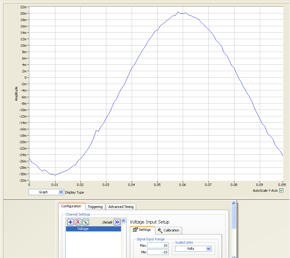
In the next screen cap, the input range was set to the minimum +/-200mV analogue input range. The data acquired using this range has a much better resolution. This is because the input voltage range defines the gain applied to the input signal.

If I were you I would define two different analogue input tasks – one with the +/-1V AI range (for use with the high-freq/high-amplitude responses), and another with +/-200mV AI range (for use with the low-freq/low-amplitude responses.)
Please note that the analogue input ranges for the PCI-6229 are: ±10, ±5, ±1, ±0.2 V
NOTE: When defining the task in measurement and automation explorer, you are able to enter any value for the input ranges. BUT don’t let this fool you, MAX simply coerces the user defined range to the nearest appropriate range list above.
Please let me know if this has an effect on your low freq acquisition.
Message Edited by RER on 05-21-2008 08:01 AM
Senior Marketing Engineer, National Instruments
Connect on LinkedIn: https://www.linkedin.com/in/richard-roberts-4176a27b/
05-21-2008 09:35 AM
- Mark as New
- Bookmark
- Subscribe
- Mute
- Subscribe to RSS Feed
- Permalink
- Report to a Moderator
06-05-2008 12:23 PM
- Mark as New
- Bookmark
- Subscribe
- Mute
- Subscribe to RSS Feed
- Permalink
- Report to a Moderator
Hi Rich,
I have finally set the input ranges of my inputs and re-run the test. Since I used DAQmx VIs in LabVIEW I had to set the inputs in the VI rather than from MAX. I still observed the jump between microphones 8 and 1 as before. Could there be any other explanation for it?
Cheers.
06-06-2008
04:48 AM
- last edited on
07-23-2025
11:27 AM
by
![]() Content Cleaner
Content Cleaner
- Mark as New
- Bookmark
- Subscribe
- Mute
- Subscribe to RSS Feed
- Permalink
- Report to a Moderator
Hi Milaero,
it sounds like a form of low-pass filter is created on the front end of your system. This will lead into ghosting between channels which will affect the measurements. Please note that the setup you are using is not
optimal for acoustic measurements as you would typically need 24-bits of resolution, anti-aliasing filters and simultaneous sampling. The following tutorial explains how you can troubleshoot the system.
https://knowledge.ni.com/KnowledgeArticleDetails?id=kA00Z000000P9mKSAS&l=en-US
KostasB
NIUK Applications Engineering
03-19-2017 04:38 PM
- Mark as New
- Bookmark
- Subscribe
- Mute
- Subscribe to RSS Feed
- Permalink
- Report to a Moderator
Hi,
just have one question. if we generate a sine waveform signal, why the maxmium singal is 20m and minimum singnal is -30ms ? I got this problem with a measurement of voltage, zero position seems not correct. How can i solve this problem. Thank you very much!.
