- Subscribe to RSS Feed
- Mark Topic as New
- Mark Topic as Read
- Float this Topic for Current User
- Bookmark
- Subscribe
- Mute
- Printer Friendly Page
how can i know that my FPGA VI logic is placed correctly on the FPGA???
05-10-2008 09:57 AM
- Mark as New
- Bookmark
- Subscribe
- Mute
- Subscribe to RSS Feed
- Permalink
- Report to a Moderator
05-10-2008 12:53 PM - edited 05-10-2008 01:01 PM
- Mark as New
- Bookmark
- Subscribe
- Mute
- Subscribe to RSS Feed
- Permalink
- Report to a Moderator
raviece54
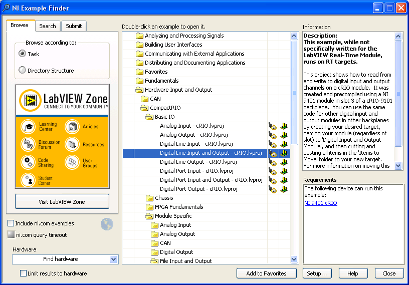
Are you setting up the line direction? You may want to try and run the example "Digital Line Input and Output.vi" from the example finder.
Message Edited by StevenA on 05-10-2008 12:01 PM
CLD
-------------------------------------
FPGA/RT/PDA/TP/DSC
-------------------------------------
05-12-2008 12:15 AM
- Mark as New
- Bookmark
- Subscribe
- Mute
- Subscribe to RSS Feed
- Permalink
- Report to a Moderator
05-12-2008 10:25 PM
- Mark as New
- Bookmark
- Subscribe
- Mute
- Subscribe to RSS Feed
- Permalink
- Report to a Moderator
Once your program is compiled (this happens when you click on the run arrow) it automatically generates the bitfile and downloads it to the FPGA. Assuming your code is written correctly, you should expect to see inputs/outpus on the NI 9401 based on the code. For debugging/testing purposes you do not need to develop an interface for the FPGA as the front panel of the FPGA VI is the interface. Once you are ready to build a complete application your interface you be developed either on the RT controller or on a host PC. As mentioned above, I would try runnning a shipping example first to make sure that your hardware is working correctly. Once you have verified that the hardware is working correctly, I would save a new copy of the example and modify it accodring to your needs.
National Instruments
Applications Engineer
05-13-2008 07:07 AM
- Mark as New
- Bookmark
- Subscribe
- Mute
- Subscribe to RSS Feed
- Permalink
- Report to a Moderator
05-13-2008 05:44 PM
- Mark as New
- Bookmark
- Subscribe
- Mute
- Subscribe to RSS Feed
- Permalink
- Report to a Moderator
National Instruments
Applications Engineer
05-13-2008 10:47 PM
- Mark as New
- Bookmark
- Subscribe
- Mute
- Subscribe to RSS Feed
- Permalink
- Report to a Moderator
I think you are working on LABVIEW8.5.
I am using LABVIEW8.0. So there is error in opening your file saying that the labview version that i am using is older version, so can not open.
How can i open that file??is there any conversion from one version to another??
If you have LABVIEW8.0..please send me in that version.
Thank you very mush Eli
Regards,
Ravi Kumar.
05-14-2008 12:58 PM
- Mark as New
- Bookmark
- Subscribe
- Mute
- Subscribe to RSS Feed
- Permalink
- Report to a Moderator
National Instruments
Applications Engineer
05-15-2008 12:07 AM
- Mark as New
- Bookmark
- Subscribe
- Mute
- Subscribe to RSS Feed
- Permalink
- Report to a Moderator
05-15-2008 04:31 PM
- Mark as New
- Bookmark
- Subscribe
- Mute
- Subscribe to RSS Feed
- Permalink
- Report to a Moderator
National Instruments
Applications Engineer
