- Subscribe to RSS Feed
- Mark Topic as New
- Mark Topic as Read
- Float this Topic for Current User
- Bookmark
- Subscribe
- Mute
- Printer Friendly Page
frequency filtering with sound card input
07-19-2005 11:41 AM
- Mark as New
- Bookmark
- Subscribe
- Mute
- Subscribe to RSS Feed
- Permalink
- Report to a Moderator
07-20-2005 09:50 PM - edited 07-20-2005 09:50 PM
- Mark as New
- Bookmark
- Subscribe
- Mute
- Subscribe to RSS Feed
- Permalink
- Report to a Moderator
The Dynamic Data type (DDT) can hold many different types of data. When you use the "Convert to Dynamic Data" Express VI, you can configure exactly how you want to interpret your data. In your case, you are converting the array to a "1D array of scalars - single channel". This basically means that you are still passing the data as an array in DDT clothes.
The issue with your VI is that you only are passing the array of data to the Filter Express VI. When this VI receives an array that doesn't hold any timing information (t0 and dt) it expects that dt is 1 second. In your case, dt is the reciprocal value of the sample rate, so you will get wrong results if you don't specify this for the Filter Express VI. What you have to do, is create a Waveform that includes the dt and the array, and then pass this Waveform to the Filter VI. Here's the easiest way to do it:
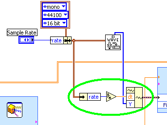
It is not necessary to specify t0 unless you need to take absolute time into account. The above changes should be enough to make your example work.
Have fun!
Message Edited by Philip C. on 07-20-2005 09:53 PM
07-21-2005 03:25 PM
- Mark as New
- Bookmark
- Subscribe
- Mute
- Subscribe to RSS Feed
- Permalink
- Report to a Moderator
Thanks so much for your input. I was starting to worry since it had been a few days and nobody replied. Your solution did work, however the filtering does not work with that setup. Do you see how to fix this problem? Also, do you know how to upsample the frequency axis (of the 3d graph) back to the original frequencies, not just the number of samples? Any hints would help a lot.
Thanks,
Daniel Felps (elen)
07-21-2005 03:27 PM
- Mark as New
- Bookmark
- Subscribe
- Mute
- Subscribe to RSS Feed
- Permalink
- Report to a Moderator
07-25-2005 01:56 AM - edited 07-25-2005 01:56 AM
- Mark as New
- Bookmark
- Subscribe
- Mute
- Subscribe to RSS Feed
- Permalink
- Report to a Moderator
I'm glad that I could help.
What do you mean with "...the filtering does not work with that setup..."? Let me know what you are expecting compared to what you are actually getting. Have you tried a small example without the 3D stuff?
I couldn't help notice that you are using a separate lowpass filter and highpass filter in your VI. You could have made it easier with only one bandpass filter instead.
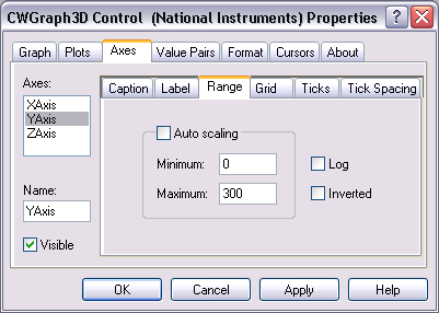
If you want to change any settings of the 3D graph, right-click on the 3D graph and choose "CWGraph3D » Properties...". You then have a lot of options to customize the graph to your needs.
Have fun!
Message Edited by Philip C. on 07-25-2005 01:57 AM
07-25-2005 09:50 AM
- Mark as New
- Bookmark
- Subscribe
- Mute
- Subscribe to RSS Feed
- Permalink
- Report to a Moderator
Daniel
