- Subscribe to RSS Feed
- Mark Topic as New
- Mark Topic as Read
- Float this Topic for Current User
- Bookmark
- Subscribe
- Mute
- Printer Friendly Page
FPGA parallel while loop + Loop Time Problem
Solved!10-22-2019 09:39 AM
- Mark as New
- Bookmark
- Subscribe
- Mute
- Subscribe to RSS Feed
- Permalink
- Report to a Moderator
Hi All,
I was sure that two parallel while loops are independent.
In my code, there is two parallel loops, One for pulse generation and another for getting the encoder values.
But, after implementation of this code, I'm not sure that parallel loops are independent. Am I right?
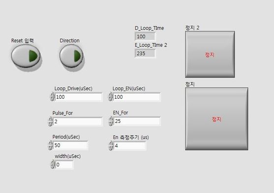
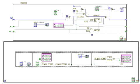
In below figure, there is two indicators: D_Loop_Time, E_Loop_Time2.
I fixed the control values for each loop timer 100us, but you can find the E_Loop_Time value is not 100us.
What is the problem of this code?
Please Help me... I'm in panic....:(
Solved! Go to Solution.
10-22-2019 09:45 AM
- Mark as New
- Bookmark
- Subscribe
- Mute
- Subscribe to RSS Feed
- Permalink
- Report to a Moderator
The loops are independent. It just appears that your second loop cannot execute that quickly.
You have at least 100us based on 25*4us waiting, and then also some digital I/O (probably quick, but depends on hardware how quick).
Additionally, this isn't a SCTL, so there are specific overheads for each loop iteration in terms of number of clock ticks (perhaps at 40MHz clock that adds a little bit... not much but still)
It appears a lot like you're overconstraining the loop times, and then somewhere an assumption isn't valid. For example, in the top loop, you have a 100us Loop Wait, combined with 2*50us waits inside the loop. This fits, but changing any of the values could make that false. The system is very brittle.
10-22-2019 10:17 AM
- Mark as New
- Bookmark
- Subscribe
- Mute
- Subscribe to RSS Feed
- Permalink
- Report to a Moderator
Thank you for quick reply.
I measured the Loop time to implement For Loop in bottom While Loop. It takes about 12us..
Your answer is correct. Thank you.
But, How can I decrease this loop time...? I am new in Labview.. So I have no idea to do this..
Can you tell me some methods?
10-22-2019 11:09 AM
- Mark as New
- Bookmark
- Subscribe
- Mute
- Subscribe to RSS Feed
- Permalink
- Report to a Moderator
Well, looking at the icon via the image, you're using Wait Until Next (or the equivalent on FPGA)? This will coerce you up to a multiple of the target 4us, not finish as quickly as possible after 4us.
What are you trying to do here? You want 25 operations evenly spread across 100us? Or you want 25 operations every 100us, and the spacing is unimportant? Or some other arrangement?
On FPGA, using a Single Cycle Timed Loop is often a key part of making things happen quickly. The below is copied from the link:
How much faster will programs execute using the SCTL?
Using a traditional While Loop in your FPGA VI takes an absolute minimum of 3 ticks to execute each iteration. This is because of the enable chain used in the compiled FPGA VI. An explanation of the enable chain is beyond the scope of this document, but is used to ensure dataflow when the FPGA VI is compiled into a bitfile.
Additionally, each function inside the While Loop will require at least one tick to execute, although functions will execute in parallel if there is no data dependency. With the SCTL, all functions inside the loop must execute within a single tick.
The first paragraph describes the extra ticks I mentioned already, but the second part describes what's probably causing your problem - you have many functions one after another that each pass data along. This adds a bunch of ticks. Using a SCTL will remove that delay, and fail to compile if it is unable to do so.
Beyond that, a SCTL can be set to use a different clock speed than your main clock speed (i.e. a multiple by some clock divisor pair). This can allow faster execution.
These topics are discussed in some length in the online FPGA training course, if you have access to that (e.g. through an SSP).
Please let me/us know regarding the desired operation - it may be there's a simple way to rewrite your code to achieve the objective/timing you want. If not, it's almost certainly possible with the SCTL.
10-22-2019 10:13 PM
- Mark as New
- Bookmark
- Subscribe
- Mute
- Subscribe to RSS Feed
- Permalink
- Report to a Moderator
Thanks, I will use the SCTL.
Can I ask one more thing?
You said that parallel while loops are independent.
If I use Hose.vi in RT and make the code to trasfer data from fpga to RT, are parallel loops in fpga also independent?
10-23-2019 12:10 AM - edited 10-23-2019 12:11 AM
- Mark as New
- Bookmark
- Subscribe
- Mute
- Subscribe to RSS Feed
- Permalink
- Report to a Moderator
@ODONG5 wrote:
Thanks, I will use the SCTL.
Can I ask one more thing?
You said that parallel while loops are independent.
Yes - that's true.
@ODONG5 wrote:
If I use Hose.vi in RT and make the code to trasfer data from fpga to RT, are parallel loops in fpga also independent?
I'm not sure which VI "Hose.vi" might be, but anything running on the FPGA is independent of the RT system except if you program it differently. Common ways to make them not independent in some way are things like handshaking systems, FIFOs, etc.
Even with communication between loops (e.g. a FIFO) you don't need them to run at the same speed. Indeed, it's very unlikely that they would - the FPGA SCTL will probably run 40000000 iterations per second (40MHz) whilst loops on the RT system are likely to be somewhat slower (especially if doing any real work).
Maybe you can describe the problem you're trying to solve and I could suggest a possible distribution of RT / FPGA code/tasks? For example:
- Reading the voltage level of the line associated with the encoder can be done in a SCTL, with a counter for number of iterations between edges. You can "average" this in whatever way you want, and every 0.1s you could send a FXP value to the RT system giving the "current" rate.
- You could customize the reporting time (the aforementioned 0.1s) using a control on the FPGA front panel. You'd need a counter in your SCTL to check when you reach a target value (so for 0.1s, you need every 4M iterations). Don't use the "i" terminal, because it will very quickly saturate (2^31 / 4*10^7 ~ 53 seconds).
- The RT system can log to disk, or stream to a computer, or both, or display a graph if you have a display connected, etc
- The RT system can do more complicated analysis perhaps (although the FPGA can also do complicated-ish analysis if you spend enough time writing the code or using the available pre-written blocks)
10-24-2019 03:19 AM
- Mark as New
- Bookmark
- Subscribe
- Mute
- Subscribe to RSS Feed
- Permalink
- Report to a Moderator
Now, I am trying to implement two tasks simultaneously. Final objective is to control the some AC Motors.
The compactRio I use is NI-9068 and I use the module NI-9403 (digital I/O) to control things.
First, I should give pulses into the motor drive.
Second, I should get the pulses from the motor drive.
In my code,
1. Load the reference input from txt file and calculate the number of pulses from the loading data.
2. (figure) Put the number of pulses into FPGA and Get the Encoder counting data from FPGA
- In FPGA, I get the value N from the RT and make N pulses. N is the value of the number of pulses from the RT.vi
- In FPGA, I get the Encoder value(T/F) from the Digital module and calculate the counting value in FPGA and then transfer it to RT.
3. Finally, in RT, I save the data (Encoder Counting value) in txt file.
Now, I can get the values from my code, but there is an delay between the input reference and encoder data and delay value is quite large.
What can I do for solving this delay?
In this example, if you suggest a possible and better method, Please tell me.
10-24-2019 05:26 AM
- Mark as New
- Bookmark
- Subscribe
- Mute
- Subscribe to RSS Feed
- Permalink
- Report to a Moderator
@ODONG5 wrote:
In my code,
1. Load the reference input from txt file and calculate the number of pulses from the loading data.
2. (figure) Put the number of pulses into FPGA and Get the Encoder counting data from FPGA
- In FPGA, I get the value N from the RT and make N pulses. N is the value of the number of pulses from the RT.vi- In FPGA, I get the Encoder value(T/F) from the Digital module and calculate the counting value in FPGA and then transfer it to RT.
3. Finally, in RT, I save the data (Encoder Counting value) in txt file.
Ok, that all sounds fine. I'm not certain about step 1, and perhaps it relates to the next part... Perhaps you can explain a little more based on my next few sentences.
@ODONG5 wrote:Now, I can get the values from my code, but there is an delay between the input reference and encoder data and delay value is quite large.
What can I do for solving this delay?
What do you mean by "delay between the input reference and encoder data"?
It sounds like you're changing a text file on the cRIO system, and then perhaps polling the text file for changes? Then carrying out the operation on FPGA, and you want to see an "encoder value". (Is this what you mean?)
The image you showed uses a While loop (you could use a For loop instead, by the way, and make it clearer that the number of iterations is fixed before the start of the loop - take care with autoindexed arrays) that contains a Wait and also iterates presumably at least a few times - it will take probably significant time to complete.
Until the While loop completes, the outputs won't become available. Is that what you mean by delay value? In this case though, you are reading the encoder data earlier - you just don't see it on the RT system.
10-24-2019 08:28 PM
- Mark as New
- Bookmark
- Subscribe
- Mute
- Subscribe to RSS Feed
- Permalink
- Report to a Moderator
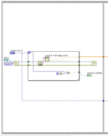
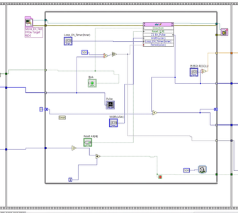
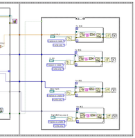
These are my code configuration.
In RT_1, I load the reference input for AC Motor from txt.file.
And, in RT_2, I want to do two tasks simultaneously using FPGA read/write function.
Two tasks are as following.
- Generating Pulse to drive
- Sensing the encoder value
Then, finally, in RT_3, I save the Sensing value to txt.file.
Implementing this code makes the result like figure as follow.
Plot blue is the reference. And Red and Green are encoder values in different mechanical conditions.
The delay that I mentioned is the gap between reference and encoder sensing value.
I want to delete this gap... This delay is not dynamic delay. It is just from the code problem.
+
Do you think that For loops are better than While loops in my code?
Actually, I used for loops first. But I changed it to while because for loops takes more ticks in code.
Am I wrong?
10-24-2019 09:18 PM
- Mark as New
- Bookmark
- Subscribe
- Mute
- Subscribe to RSS Feed
- Permalink
- Report to a Moderator
Please attach the VIs.
Trying to follow through the pictures is quite difficult, and open to misinterpretation. In particular, it looks like RT_3 is the frame following RT_2, but RT_1 outputs a floating point array, and then RT_2 receives a boolean and an integer array, so they are not the same structure (or at least, they have a missing middle frame, or were taken from different times in your project).
Thank you for the graphs - that makes it a little clearer.


