- Document History
- Subscribe to RSS Feed
- Mark as New
- Mark as Read
- Bookmark
- Subscribe
- Printer Friendly Page
- Report to a Moderator
- Subscribe to RSS Feed
- Mark as New
- Mark as Read
- Bookmark
- Subscribe
- Printer Friendly Page
- Report to a Moderator
Vision based quadcopter control system using LabVIEW and myRIO
Contact Information
Competition Year: 2016
University: University of Portsmouth
Team Members: Sean Fuller (2016)
Faculty Advisers: Hassan Parchizadeh
Email Address: seanfuller@outlook.com
Country: UK
Project Information
Title: Vision based quadcopter control system using LabVIEW and myRIO
Description: Determine whether image processing could be used as a more accurate alternative to GPS for tracking and controlling a quadcopters position.
Products:
Hardware
- NI myRIO
- Hubsan X4 quadcopter
- Hubsan X4 quadcopter controller
- Logitech Quickcam Pro 5000
Software
- NI LabVIEW
- NI Vision Development Module
- MyRIO Toolkit
- PID and Fuzzy Logic Toolkit
- Real-Time Module
The Challenge:
With the sale of quadcopters projected to increase by 50% in the next six years to $12 billion, numerous companies such as Google and Amazon are investigating how they can integrate this technology into their current businesses. Quadcopters conventionally use a global positioning system (GPS) in order to determine position and have a horizontal accuracy of three meters or better, 95% of the time. By improving this accuracy using image processing, this would allow industries to harness the power of quadcopters to cut down on costs and improve on safety.
The Solution:
Using a single commercially available webcam with NI LabVIEW and a myRIO, a 3D-localisation, tracking, and control system was implemented which successfully controlled the position of the quadcopter in real-time.

Overview of project with myRIO in the foreground and quadcopter in the background
The image acquired from the camera was converted to grayscale and processed using the image processing algorithm designed for this project. From this, the quadcopters position was extracted and compared against the user defined set-position on the front panel.
Project in action
Video of project working
How was the image processing achieved?
NI Vision Assistant was a key tool in designing an algorithm both fast and reliable enough to control the quadcopter. Geometric matching which is native to NI Vision Assistant was used to design a template image which the real-time acquired image was compared against. From this algorithm, the quadcopters yaw, height, x and y-coordinate was obtained.

User interface
Geometric matching was selected as the most suitable image processing algorithm for this application as it could locate the quadcopter even when tilted and partially obstructed making the system extremely robust. Using NI Vision Assistant, the template image was designed using the live interface which made identifying the most optimal values extremely fast for prototyping. The image processing identified the quadcopter by looking for edges in the images. These edges were then compared against the template image and from this, was able to determine whether the quadcopter was present, and if so, the position of it.
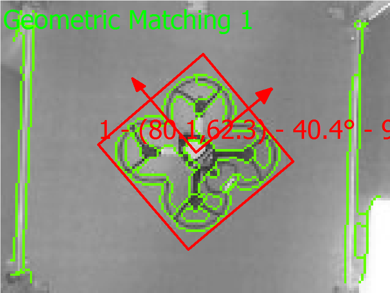
Screenshot from NI Vision Assistant of image processing
Interfacing between the myRIO and quadcopter controller
The quadcopter controller gave the operator control over the quadcopters height, yaw, roll and pitch via two joysticks.

Quadcopter controller with joysticks attached
These two joysticks control four potentiometers which output a 0-5V signal. By removing these potentiometers, four of the myRIOs analogue output pins were connected directly to the quadcopter controller. Using LabVIEW, these output pins were configured to be limited to 0-5V to emulate the potentiometers.

myRIO connected to quadcopter controller
PID controller
The PID controller was implemented using the PID and Fuzzy Logic toolkit. This made it quick and easy to input PID values and analyse the quadcopters response from the front panel. By doing so, the PID controller was tuned which controlled the quadcopter in a responsive and stable manner.
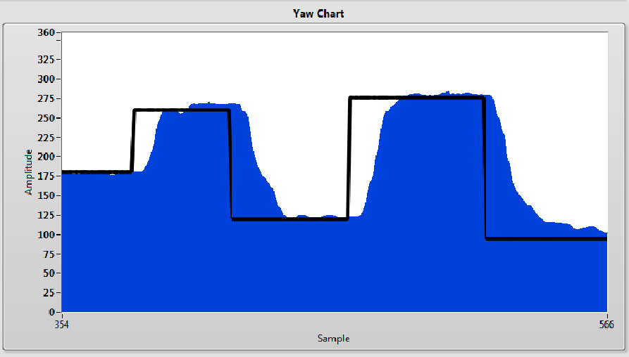
PID yaw response
Why LabVIEW?
The project involved countless tests and design iterations and therefore LabVIEW was well suited due to the intuitive graphical programming and built-in debugging tools. This meant that less time was spent fixing problems and more time was spent on optimising the system to maximise the performance.
The myRIO toolkit meant that programming and interfacing between the myRIO and laptop was quick to set up and provided a live stream of real-time information to the user interface.
What’s next?
This project implemented a single PID control system which controlled the yaw of the quadcopter. Therefore, the other height, roll and pitch were kept at constant values and the quadcopter was held in position so that the yaw could be controlled. The height, x and y-coordinate information was extracted from the image processing therefore using this, the quadcopters height, roll and pitch could all be controlled. This would require further tuning of PID values, however with LabVIEW, prototyping and tuning will be fast.
Industry application
This type of image processing system would be ideal for industries with either dangerous or hard to reach areas. Power plant chimneys regularly need to be inspected both inside and out for signs of wear and cracks. By using this system, a quadcopter with a built-in camera could be sent up the chimneys while the camera at the bottom of the chimney controls the quadcopters position. This would allow for closer up detailed imagery when compared with a GPS quadcopter as the accuracy is much more precise using image processing. By automating the process with image processing, the cost of maintenance is driven down and therefore opens the possibility to more regular inspections and in turn, issues will be detected quicker which will reduce the overall impact of any problems which arise.
Project poster

- Mark as Read
- Mark as New
- Bookmark
- Permalink
- Report to a Moderator
Fast image processing and tight control of the Quadcoptor. I also like how you hacked the original Quadcoptor controller. Ingenious piece of engineering. Congratulations!
Senior Marketing Engineer, National Instruments
Connect on LinkedIn: https://www.linkedin.com/in/richard-roberts-4176a27b/
- Mark as Read
- Mark as New
- Bookmark
- Permalink
- Report to a Moderator
Great project Sean!
- Mark as Read
- Mark as New
- Bookmark
- Permalink
- Report to a Moderator
Can you give me a PID control file?
thank!
