- Document History
- Subscribe to RSS Feed
- Mark as New
- Mark as Read
- Bookmark
- Subscribe
- Printer Friendly Page
- Report to a Moderator
- Subscribe to RSS Feed
- Mark as New
- Mark as Read
- Bookmark
- Subscribe
- Printer Friendly Page
- Report to a Moderator
Example Arduino: analog input + serial interface to LabVIEW
Description
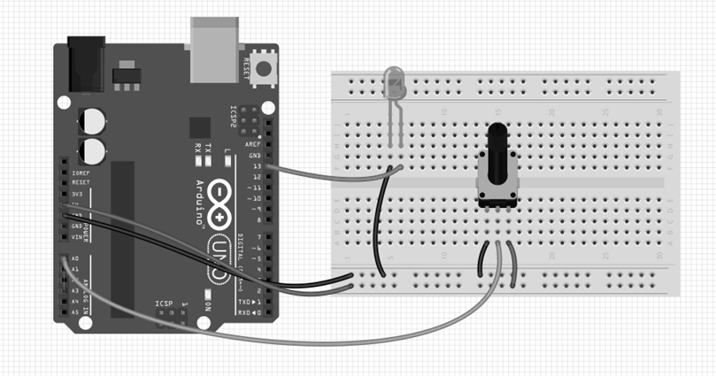
This article presents a procedure for reading an analog port on the Arduino UNO R3 board , the analog data will be sent via serial communication to the PC and can be monitored from the front panel of our program through a graph indicator .

Procedure
First we note that analog data work and these can vary from 0 - 5VDC, for this type of data can be used a potentiometer or a variable source if we have it, for this example we will use a potentiometer and voltage is obtained from Arduino same card .
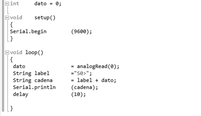
We will use the provided software developers Arduino, to conduct the program reading the analog port A0 . For the development of our program we note that the value obtained in the analog port is a value between 0 and 1023, then a fragment program that will download into the microcontroller.

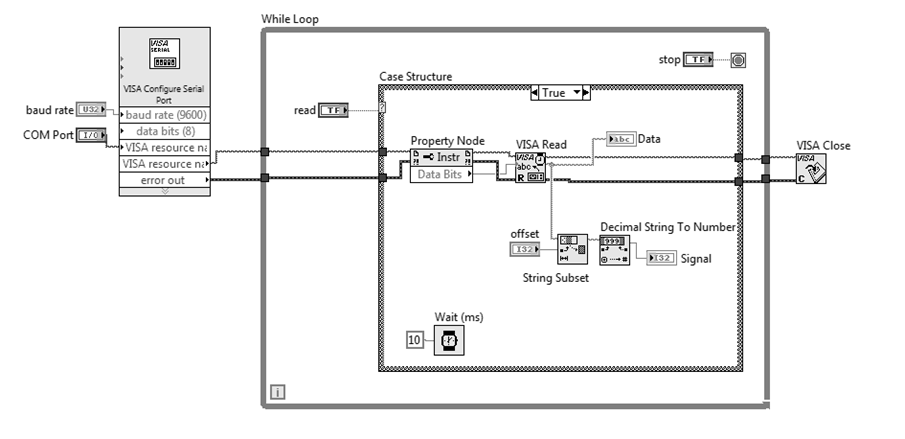
Make a program in LabVIEW to test and verify the correct operation of our program in the Arduino , we will make the reading of data transmitted by the Arduino from the serial port on the card installed , proceed to read the COM port

- Mark as Read
- Mark as New
- Bookmark
- Permalink
- Report to a Moderator
Before interfacing with labview and arduino, is this need to download this program source code to the arduino uno microcontroller? thank you very much.
- Mark as Read
- Mark as New
- Bookmark
- Permalink
- Report to a Moderator
This example does not use LIFA. So yes you need to compile and upload the sketch shown above to your Arduino board before connecting the Arduino board to Labview.
hrh1818
- Mark as Read
- Mark as New
- Bookmark
- Permalink
- Report to a Moderator
On Labview, the integer "signal" seems to be connected on wrong pin (offset instead number).
- Mark as Read
- Mark as New
- Bookmark
- Permalink
- Report to a Moderator
I have Read 220 rms voltage from Arduino using serial monitor. Now i want to display it on Labview so can anyone help me with that
