- Subscribe to RSS Feed
- Mark Topic as New
- Mark Topic as Read
- Float this Topic for Current User
- Bookmark
- Subscribe
- Mute
- Printer Friendly Page
cRIO 9073 remote subnet tutorial
12-27-2010 12:32 PM
- Mark as New
- Bookmark
- Subscribe
- Mute
- Subscribe to RSS Feed
- Permalink
- Report to a Moderator
hey all,
I am trying to use a cRIO 9073 on a remote subnet.
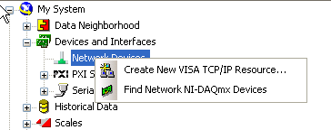
So far I am able to add under New/Targets and Devices.../Existing target or device/Specify a target or IP/Real-time CompactRIO (see image #1 below).
It appears with a turned off green light, but as I 'connect' to it (image #2 below), it goes active (image #3 below), after completing some automatic steps.
Now, my questions are: so now what? is there a tutorial on how to proceed from here?
I've been looking around and all I found was how to interact with the thing over the same subnet.
Note that I have two C series modules on it, the NI-9217 and the NI-9203.
thank you for all your help,
Adrian
12-28-2010 10:51 AM
- Mark as New
- Bookmark
- Subscribe
- Mute
- Subscribe to RSS Feed
- Permalink
- Report to a Moderator
Adrian,
What exactly are you trying to do? The first thing you probably want to do if you have not used this module before is to make sure that all of the software is up to date. To do this, go into MAX, select "Remote Systems", find your device under the remote system and expand the system. Locate "Software" under you system, right click and select "Add/Remove Software" and then update add software as necessary. The software you will need will depend on what you intend to do. For instance, if you intend to use shared variabels for communication, you will need the "Network Variable Engine".
In addition to updating the software in MAX, you should make sure that the system is correctly identified under "Devices and Interfaces". This will allow you to correctly configure the system for communication.
And now that everything is properly identified, you can start your programming. Programming this device is similar to programming in the standard LV environment except that you are restricted to using methods and properties not associated with user interfaces (for example, you can not use a property node to update a control). This is because in the real time environment (what is running on the cRIO), there are no user interfaces.
Finally, you will also have to decide how you communicate with your different modules. On the cRIO, you can either use the scan interface which will allow you to just pull the data off as you would in DAQ or you can use the FPGA interface which will allow you to exploit the capabilities of the FPGA on the chassis backplane. The FPGA will allow you to do more in the hardware (such as averaging measurements, performing transforms, etc) and free up limited CPU time on the controller itself. This decision also has impacts for what software you will load on the controller (as above) and what software you will need to program the device. If you do not have the LV FPGA module then the decision is made for you - scan interface.
Anyway, I apologize if these are things that you were already aware of or this did not answer your question. But, I hope this helps.
Cheers, Matt
12-28-2010 11:06 AM
- Mark as New
- Bookmark
- Subscribe
- Mute
- Subscribe to RSS Feed
- Permalink
- Report to a Moderator
cloharsro wrote:
Now, my questions are: so now what? is there a tutorial on how to proceed from here?
I've been looking around and all I found was how to interact with the thing over the same subnet.
In general, once you have added the target to your project and are able to connect to it, it doesn't make a difference whether it is on the local subnet or a different remote subnet.
Most functions for communicating with the target (shared variables, TCP, network streams, etc.) will works the same.There are a few functions like UDP Broadcast that will work differently, i.e. are not supported for remote subnets.
Assuming you are familiar with LV and LV RT programming, looks for information on the following communication topics.
Shared Variables
TCP/UDP
Network Streams (LV 2010 feature)
Also the following document may help.
Using the Right Networking Protocol
Christian L, CLA
Systems Engineering Manager - Automotive and Transportation
NI - Austin, TX
12-28-2010 11:14 AM
- Mark as New
- Bookmark
- Subscribe
- Mute
- Subscribe to RSS Feed
- Permalink
- Report to a Moderator
The one thing that used to be different (not sure if it still is) is that you couldn't install software on a remote target from MAX, therefore, you had to hook up on a local subnet (with a crossover cable for instance) to install the initial software and then you could put it on the remote subnet for everything else.
12-28-2010 10:13 PM
- Mark as New
- Bookmark
- Subscribe
- Mute
- Subscribe to RSS Feed
- Permalink
- Report to a Moderator
What exactly are you trying to do? The first thing you probably want to do if you have not used this module before is to make sure that all of the software is up to date. To do this, go into MAX, select "Remote Systems", find your device under the remote system and expand the system. Locate "Software" under you system, right click and select "Add/Remove Software" and then update add software as necessary. The software you will need will depend on what you intend to do. For instance, if you intend to use shared variabels for communication, you will need the "Network Variable Engine".
I have to read temperature and water flow from two sensors (RTD and current output respectively). This is a set-up for a machine room of a builduing and there is an Ethernet connection available.
I'm thinking that the cRIO could do some processing and then ship/upload the information (using a specific format) to a certain website.
Now, the software I have installed, is the one that came with the thing is shown in image #1. I actually don't know if it's what I need or where can I find more (should I require it).
image #1

In addition to updating the software in MAX, you should make sure that the system is correctly identified under "Devices and Interfaces". This will allow you to correctly configure the system for communication.
what exactly do you mean 'correctly identified'? And is it the 'devices and interfaces' on top, or the one below, under 'remote systems'?
I attempted to add it in the one above, but I am without connection with the thing (for some reason it shows up as disconnected), so I wasn't unable to. Just in case, I leave an image of where I attempted it, to confirm the step (see image # 2 below).
image #2
And now that everything is properly identified, you can start your programming. Programming this device is similar to programming in the standard LV environment except that you are restricted to using methods and properties not associated with user interfaces (for example, you can not use a property node to update a control). This is because in the real time environment (what is running on the cRIO), there are no user interfaces.
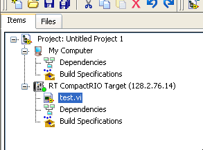
so at this point I guess that I need to create a new project, add the thing as a new device, and create a VI for it (see images #3 & #4 below). Is this it?
image #3
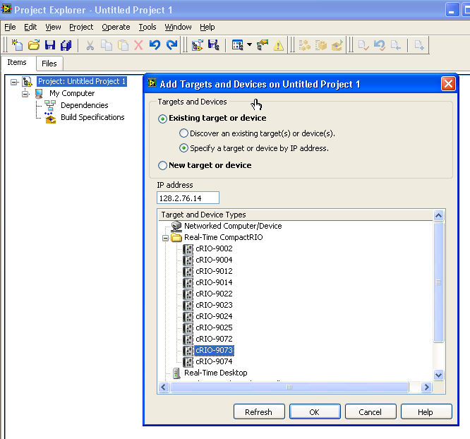
image #4 - note that the green light is lit so I should be good, right?
Finally, you will also have to decide how you communicate with your different modules. On the cRIO, you can either use the scan interface which will allow you to just pull the data off as you would in DAQ or you can use the FPGA interface which will allow you to exploit the capabilities of the FPGA on the chassis backplane. The FPGA will allow you to do more in the hardware (such as averaging measurements, performing transforms, etc) and free up limited CPU time on the controller itself. This decision also has impacts for what software you will load on the controller (as above) and what software you will need to program the device. If you do not have the LV FPGA module then the decision is made for you - scan interface.
yes, I would like to do some processing, especially since there's not going to be a host that will do any processing, but simply a website that expects a certain file format for publishing. So I would encapsulate the information from the cRIO and ship it that way.
Since I am positive I have the FPGA module, that should be it then, FPGA all the way.
Again, thank you very much Matt for this whole insight, and just to finalize, my biggest issue right now is the one described on image #4 (is that the way to do it)?
Adrian
12-28-2010 10:16 PM
- Mark as New
- Bookmark
- Subscribe
- Mute
- Subscribe to RSS Feed
- Permalink
- Report to a Moderator
In general, once you have added the target to your project and are able to connect to it, it doesn't make a difference whether it is on the local subnet or a different remote subnet.
Most functions for communicating with the target (shared variables, TCP, network streams, etc.) will works the same.There are a few functions like UDP Broadcast that will work differently, i.e. are not supported for remote subnets.
that is good news then.
About the rest of the things you suggested, I will try to give them a look.
Thank you for your help so far.
Adrian
12-28-2010 10:18 PM
- Mark as New
- Bookmark
- Subscribe
- Mute
- Subscribe to RSS Feed
- Permalink
- Report to a Moderator
The one thing that used to be different (not sure if it still is) is that you couldn't install software on a remote target from MAX, therefore, you had to hook up on a local subnet (with a crossover cable for instance) to install the initial software and then you could put it on the remote subnet for everything else.
done that, but thanks anyway for the help.
Adrian
12-29-2010 09:39 AM
- Mark as New
- Bookmark
- Subscribe
- Mute
- Subscribe to RSS Feed
- Permalink
- Report to a Moderator
You might want to install a bit more software on the target. You can do that by right-clicking the software tab in MAX and selecting Add/Remove software and then selecting one of the basic stacks in place of the minimal one or adding the things you need one by one through the custom installation. At a minimum, I would recommend adding the following:
* NI-Watchdog - This allows you to create a watchdog for your system that will reboot it in the event of a crash. Unless you plan to write your own watchdog using the FPGA then this component is a must for any system which is intended to run for long periods of time, which I suspect yours is.
* System State Publisher - This allows you to view the memory and CPU usage of your system in the distributed system manager, which is very helpful for debugging. It's also very helpful if you end up using scan engine. I would at least install it during your development process, you could protentially remove it to save a little bit of space and processor resources for your deployed application.
Other components that you might need:
* NI Scan Engine and NI-RIO IO Scan - Unless you need to read your water flow sensor more than 1000 times per second I suggest you start by using the NI Scan Engine. You can still do processing on the RT system, but I haven't seen anything in your description so far that suggests you need to write code for the FPGA. FPGA programming will significantly increase your development time because there is some increased learning curve for it and because you need to compile FPGA code, a process which takes between 10 minutes and a couple of hours each time you change something. LabVIEW FPGA is a really powerful tool, but you shouldn't use it unless you have to.
* Web Server for LabVIEW RT and Run-Time Engine for Web Services - These are probably the simplest way to get data from your system to a web page. Web services allow you to publish data to web accessible variables that you can subscribe to in a web page.
Once again, you may need to put the system temporarily on a local subnet or cross-over to modify the software installed.
To answer some of your other questions:
1. cRIO systems don't show up under the My System view, only Remote Systems. There is not much to look at in the Devices and Interfaces tab of a cRIO, as long as the Status of the FPGA reads "This device is working properly." you are good to go, but it's fairly rare to have any problems reported here. PXI RT systems use the Devices and Interfaces tab more than cRIO.
2. You are correct in that the green light in the project is good. The next thing you need to do is probably to add your chassis to the project (by right-clicking the cRIO and selecting New Target or Device) so that you can start getting access to your I/O. Before doing that, decide whether you are going to use scan engine or FPGA, as it will ask you to choose (assuming you install the scan engine components as mentioned above). Once you have access to your I/O a good start would be to try to display a voltage or temperature reading on the front-panel of the RT VI.
If you haven't already found it, the cRIO Developer's Guide is a good resource http://www.ni.com/compactriodevguide/ although it uses shared variables for much of its communication which probably won't be apropriate for you since you need to get the data to a web page.
01-05-2011 08:31 PM
- Mark as New
- Bookmark
- Subscribe
- Mute
- Subscribe to RSS Feed
- Permalink
- Report to a Moderator
First of all, allow me just to thank you for your really explicit and good reply. Thank you!
Now, I have a few comments, if you will:
You might want to install a bit more software on the target. You can do that by right-clicking the software tab in MAX and selecting Add/Remove software and then selecting one of the basic stacks in place of the minimal one or adding the things you need one by one through the custom installation. At a minimum, I would recommend adding the following:
* NI-Watchdog - This allows you to create a watchdog for your system that will reboot it in the event of a crash. Unless you plan to write your own watchdog using the FPGA then this component is a must for any system which is intended to run for long periods of time, which I suspect yours is.
* System State Publisher - This allows you to view the memory and CPU usage of your system in the distributed system manager, which is very helpful for debugging. It's also very helpful if you end up using scan engine. I would at least install it during your development process, you could protentially remove it to save a little bit of space and processor resources for your deployed application.
where do I find this software? Do I buy it from some where, or is it offered with the cRIO itself?
* NI Scan Engine and NI-RIO IO Scan - Unless you need to read your water flow sensor more than 1000 times per second I suggest you start by using the NI Scan Engine. You can still do processing on the RT system, but I haven't seen anything in your description so far that suggests you need to write code for the FPGA. FPGA programming will significantly increase your development time because there is some increased learning curve for it and because you need to compile FPGA code, a process which takes between 10 minutes and a couple of hours each time you change something. LabVIEW FPGA is a really powerful tool, but you shouldn't use it unless you have to.
* Web Server for LabVIEW RT and Run-Time Engine for Web Services - These are probably the simplest way to get data from your system to a web page. Web services allow you to publish data to web accessible variables that you can subscribe to in a web page.
agreed! thanks again for the good input!
01-05-2011 10:31 PM
- Mark as New
- Bookmark
- Subscribe
- Mute
- Subscribe to RSS Feed
- Permalink
- Report to a Moderator
cloharsro wrote:
where do I find this software? Do I buy it from some where, or is it offered with the cRIO itself?
* NI Scan Engine and NI-RIO IO Scan - Unless you need to read your water flow sensor more than 1000 times per second I suggest you start by using the NI Scan Engine. You can still do processing on the RT system, but I haven't seen anything in your description so far that suggests you need to write code for the FPGA. FPGA programming will significantly increase your development time because there is some increased learning curve for it and because you need to compile FPGA code, a process which takes between 10 minutes and a couple of hours each time you change something. LabVIEW FPGA is a really powerful tool, but you shouldn't use it unless you have to.
agreed! thanks again for the good input!
The software would ship with LV - it would be located with the RT software that you installed (I believe).
And regarding Ryan's comment on the FPGA - definitely true. Don't jump in if you don't have really tight timing requirements or have a need to offload some of the computation (due to limited CPU power or whatnot).
Cheers, Matt
