- Subscribe to RSS Feed
- Mark Topic as New
- Mark Topic as Read
- Float this Topic for Current User
- Bookmark
- Subscribe
- Mute
- Printer Friendly Page
Using the LabVIEW 2012 FPGA Control on CompactRIO Sample Project
07-24-2012 02:04 PM
- Mark as New
- Bookmark
- Subscribe
- Mute
- Subscribe to RSS Feed
- Permalink
- Report to a Moderator
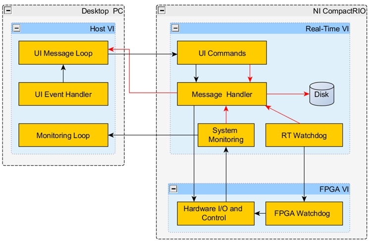
The attached document goes into detail on the architecture of the LabVIEW FPGA Control on CompactRIO sample project. You can see from the diagram below that this sample project has VIs running on three different targets: the desktop PC, the CompactRIO Real-Time target, and the CompactRIO FPGA target. This document also provides best practices and coding techniques throughout.
08-02-2012 10:20 PM
- Mark as New
- Bookmark
- Subscribe
- Mute
- Subscribe to RSS Feed
- Permalink
- Report to a Moderator
Will this work for FPGA on a PXI-based RT system? Say with a 7854R or equivalent?
08-03-2012 09:56 AM
- Mark as New
- Bookmark
- Subscribe
- Mute
- Subscribe to RSS Feed
- Permalink
- Report to a Moderator
Everything should work great except the "System Reset" node on the LabVIEW FPGA Main.vi only works on CompactRIO and Single-Board RIO targets.
08-03-2012 10:05 AM
- Mark as New
- Bookmark
- Subscribe
- Mute
- Subscribe to RSS Feed
- Permalink
- Report to a Moderator
Meghan, it might be informative to the novice user if you put that node inside a Conditional Disable structure that cases on the target type.
08-03-2012 10:17 AM
- Mark as New
- Bookmark
- Subscribe
- Mute
- Subscribe to RSS Feed
- Permalink
- Report to a Moderator
That's great feedback, I will try to make this change in the next revision. Thanks David!
08-03-2012 10:27 AM
- Mark as New
- Bookmark
- Subscribe
- Mute
- Subscribe to RSS Feed
- Permalink
- Report to a Moderator
Can we have these documents as platform-independent file formats please, such as PDF.
08-03-2012 01:44 PM
- Mark as New
- Bookmark
- Subscribe
- Mute
- Subscribe to RSS Feed
- Permalink
- Report to a Moderator
I uploaded this document as a PDF, but unfortunately the images are somewhat blurry and I'm not sure how to fix them.
10-13-2012 08:20 PM
- Mark as New
- Bookmark
- Subscribe
- Mute
- Subscribe to RSS Feed
- Permalink
- Report to a Moderator
So why have you used a shift register as opposed to a tunnel for the error cluster in the "UI Message Loop" when you are clearing the errors right before they reach the right-side shift register terminal? I'm guessing that any further use of this particular error data stream to the right of the loop is purely to establish execution precedence.
10-15-2012 10:52 AM
- Mark as New
- Bookmark
- Subscribe
- Mute
- Subscribe to RSS Feed
- Permalink
- Report to a Moderator
Here's a screenshot of the relevant part of the UI Main.vi block diagram (with subVI labels shown for clarity):
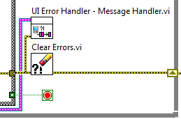
This VI was built from the Queued Message Handler desktop project template. The desktop template uses the shift register to pass the error cluster to the next iteration, where it is handled in the Dequeue Message.vi (not shown). For the FPGA Control sample project, we wanted to implement more sophisticated error handling...that's why we have the UI Error Handler - Message Handler.vi, which processes errors into different categories, and sends one of several error-related messages back to the message handler for further processing. Instead of changing the existing message handling API when I added the new error handling scheme to this sample project, I just left it there, but I effectively disabled it with the Clear Errors.vi.
In case it wasn't clear by now, I wrote this sample project.  Let me know if you have any other questions.
09-13-2013 06:52 AM
- Mark as New
- Bookmark
- Subscribe
- Mute
- Subscribe to RSS Feed
- Permalink
- Report to a Moderator
Hi,
How does the "Change State" (in FPGA) come back to the FALSE value? I mean: When there is a State Change in the FPGA ordered from the RT Main, the RT Main changes the value from "Change State" to TRUE (There is a change in the state, obvious), but never sets it back to FALSE, which would mean that the FPGA is continiously checking change to the new state... Right? Or i am missing something?
Thanks!
