VGA Device Driver for FPGA Applications
- Subscribe to RSS Feed
- Mark as New
- Mark as Read
- Bookmark
- Subscribe
- Printer Friendly Page
- Report to a Moderator
Code and Documents
Attachment
Synopsis
The 'Manage VGA' subVI drives the VGA port signal lines to create a 640x480 3-bit video image from a user-supplied FPGA circuit.
Description
The VGA port signals include two synchronization signals (vertical sync and horizontal sync) and three color signals (red, green, and blue). The subVI ‘Manage VGA’ creates the the sync signals for a 640x480 resolution image, and provides two numerical outputs to indicate the current pixel location. The pixel begins each video frame at the origin in the upper left corner of the display, and moves left-to-right and then top-to-bottom in a raster pattern. The "pixel column" output ranges from 0 at the top of the image to 639 at the bottom, and the "pixel row" output ranges from 0 at the left side of the image to 479 at the right side. User-supplied circuitry converts the current pixel column and row values into the desired pixel color (RGB value) to be displayed at that pixel location and applies that 3-bit pattern to the inputs of the subVI.

The wrapper subVI ‘Manage VGA (Spartan-3E Starter Kit)’ bundles ‘Manage VGA’ and the FPGA I/O nodes for the Spartan-3E Starter Kit FPGA board VGA port to provide a convenient interface to the VGA port.
.png)
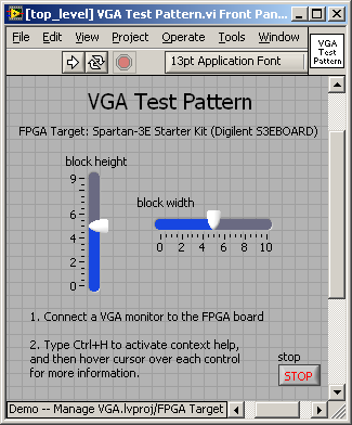
The included application VI ‘VGA Test Pattern’ demonstrates the subVI with a colorful mosaic pattern on the Spartan-3E Starter Kit (Digilent S3EBOARD).


Steps to Complete: Running the Demonstration
1. Download Demo -- Manage VGA.zip and extract to a suitable folder
2. Open Demo -- Manage VGA.lvproj
3. Open the Top-Level VIs virtual folder, and then open and run [top_level] VGA Test Pattern.vi
4. Connect a VGA monitor to the VGA port connector on the Spartan-3E Starter Kit FPGA board.
5. Operate the slider controls on the front panel display to adjust the size of the mosaic blocks.
Steps to Complete: Using ‘Manage VGA’ in your own application
1. Open your existing LabVIEW project that includes an FPGA target (the target must have a VGA port, such as the Spartan-3E Starter Kit)
2. Right-click on FPGA Target and choose Add File
3. Select the files Manage VGA.vi and Manage VGA (Spartan-3E Starter Board).vi from the .zip distribution
4. Add the required FPGA I/O resources for VGA: Right-click on FPGA Target, select New and then FPGA I/O, select VGA Port, click the right-pointing arrow, and then click OK
5. Open your application VI
6. Select the block diagram, right-click on an open area, choose Select a VI, and then select Manage VGA (Spartan-3E Starter Board).vi
7. Ensure that the subVI is contained within a single-cycle timed loop operating at 50 MHz
8. Create circuitry that drives the red, green, and blue inputs of Manage VGA (Spartan-3E Starter Board) based on the current pixel row and column indicated by the same subVI; note that using the current pixel and row is not required if you wish to apply a constant color or use some other means to determine the color at each pixel.
Requirements
This subVI must reside within a single-cycle timed loop operating at 50-MHz. Changing the clock frequency requires changing selected constants within the subVI.
References
1. ‘Manage VGA’ translates the Verilog module "VGA.v" available here: http://ecen3233.okstate.edu/Fall%202006/Verilog%20Files/VGA.zip; documentation for this module is also available: http://ecen3233.okstate.edu/Fall%202006/PDF/VGA%20Module%20Tutorial.pdf.
2. See Chapter 6 of the Spartan-3E Starter Kit Reference Manual for a complete discussion of VGA signal timing requirements. If the reference manual link has changed, refer to the “Support” section of the Digilent website.
Example code from the Example Code Exchange in the NI Community is licensed with the MIT license.
- Mark as Read
- Mark as New
- Bookmark
- Permalink
- Report to a Moderator
Hey!
do you know how to apply this, but the display from VGA will show image?
like image from my PC file
great job btw, thanks!
