Using the Kinect with LabVIEW and the Upgraded Microsoft .NET API
- Subscribe to RSS Feed
- Mark as New
- Mark as Read
- Bookmark
- Subscribe
- Printer Friendly Page
- Report to a Moderator
Products and Environment
This section reflects the products and operating system used to create the example.To download NI software, including the products shown below, visit ni.com/downloads.
- Microsoft Kinect
Other
Code and Documents
Attachment
Description
Description-Separate-1There have been a few versions of Kinect wrappers for LabVIEW circulating since the original release of the Kinect. Many had advantages others did not (I, personally, wrote one of them), but none take advantage of the new upgrades to the Microsoft Kinect API (which actually broke some previous versions of the Kinect API). The library outlined here gives much of the basic functionality users are looking for when using the Kinect.
Features Include:
-Get information on any Kinect Devices attached to the computer.
-Connect to any of a number of Kinects attached to the computer.
-Get the Color Images from the Kinect in any of the supported formats.
-Get the Depth Images from the Kinect in any of the supported formats.
-Get the approximate location of a speaking user using the Kinect Audio API.
-Set the angle of elevation of the Kinect.
-Basic error handling.
Missing/Incomplete features:
-Get the RAW audio information from the Kinect Microphones
-Get the Skeletal frame from the Kinect (this feature was started, but is incomplete - completing the VI is left as an exercise to the user).
-Perform speech recognition automatically using the API.
The VIs are documented internally but are outlined breifly here. The example VI is provided which is also explained here.
This software requires NI Vision Acquistion Software (specifically NI IMAQ) which can be downloaded for free from ni.com/drivers.
This software was constructed in LabVIEW 2011 SP1 and requires the .NET 4.0 configuration file to have been set for LabVIEW (see this article on how to do that).
The example:
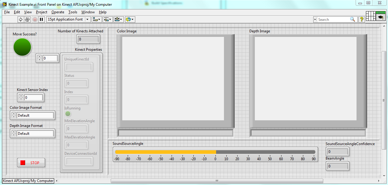
The front panel consists of a settings panel on the left which demos some basic features including the ability to select a specific Kinect, Color Image Format and Depth Image Format. The approximate location of the user based on the sound the produce is revealed on the bottom as well as the confidence and the beam angle. Unlike with previous iterations involving the .NET API, this package does not crash as a result of hitting the Abort button instead of the Stop button (as is recommended to avoid memory leaking).
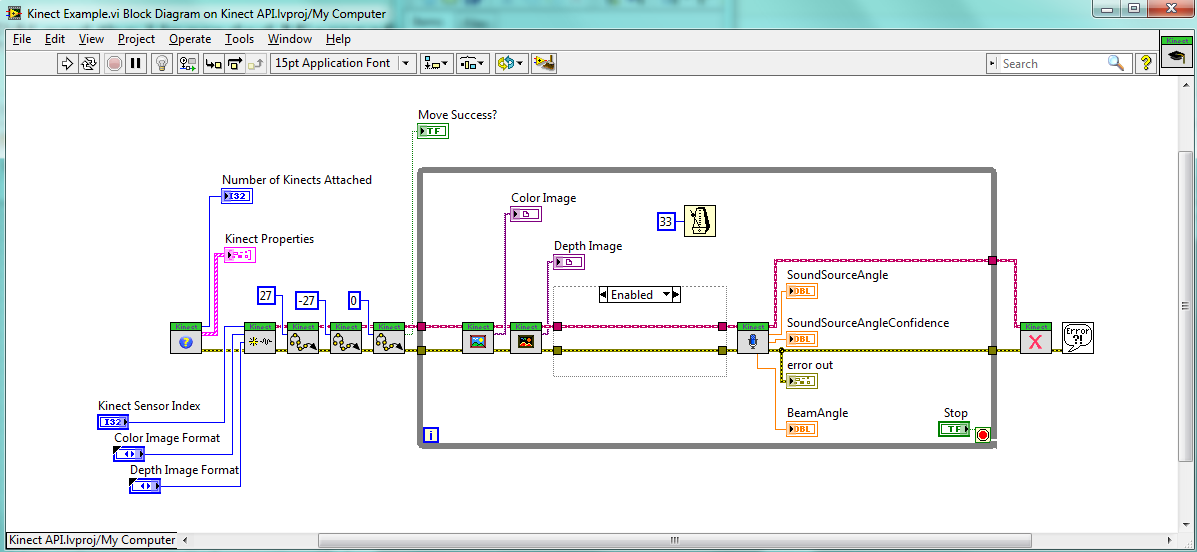
As we can see, the block diagram follows a very simple structure familiar to all of us. The first VI gets the information on the Kinects we have connected to the machine (this has only been tested with one Kinect as it's all I have). The second initializes a connection to the selected Kinect (typically Index 0) and selects the resolutions we want. The next three VIs perform some example movements of the Kinect's tilt motor. Notice the min and max range are populated in the Get Device Info.vi function.
The loop repeatedly gets the color frame, depth frame and audio information. The Dispose function stops all sensors and the Kinect and clears any internal errors we created (leaving only non-handled errors).
Note the delay we left in the loop. This prevents the color and depth frames from repeatedly throwing errors from being called too fast. You can tweak this speed to your preference, but if called too quickly, the Get functions will return non-fatal errors.
The disabled area within the block diagram is a short attempt to get the Skeletal Frame. It is not working and not tested, but provided as a starting point for those considering pulling this information.
The wrapper provides a session wire which can be called using a property node to get some basic information. These values cannot be written with a property node, but write functionality is included in the form of VIs which can be found in the Kinect Session class.
Remember you must install the Microsoft Kinect API in order for this package to work. Additionally, this has not been tested on a 64 bit machine. You may need to remap the DLL reference in order for this to work.
Happy Kinecting!
Install Instructions
___________________________________________________________
-Install LabVIEW 2011 SP1.
-Install Vision Acquistion Software (Specifically NI IMAQ - this is free).
-Install The Microsoft Kinect API (v1.0 - installer attached).
-Install .NET 4.0 and add the config file to the LabVIEW.exe directory.
-Load the Library and try the example.
Description-Separate-2Example code from the Example Code Exchange in the NI Community is licensed with the MIT license.
- Mark as Read
- Mark as New
- Bookmark
- Permalink
- Report to a Moderator
Looks great, can't wait to try it out!
- Mark as Read
- Mark as New
- Bookmark
- Permalink
- Report to a Moderator
I am Trying to use this instruction in the 64bit OS please guide me more how can I do this?
I follow above instruction in my 64bit system win7 and just get a bit response in initializing the
kinect sensor.
PLease give me a guidance in :
"Additionally, this has not been tested on a 64 bit machine. You may need to remap the DLL reference in order for this to work."
thanks,
Saeed
- Mark as Read
- Mark as New
- Bookmark
- Permalink
- Report to a Moderator
when I try to get the depth image I face to this error:
inect Library.lvlib:Get Depth Frame.vi<ERR>
There was an error reading the Depth Image from the Kinect.
This could be caused by attempting to read the image too quickly
or an issue with the connection to the Kinect.
- Mark as Read
- Mark as New
- Bookmark
- Permalink
- Report to a Moderator
I can confirm this works with LabVIEW 2011 SP1 on Windows x64 with the latest SDK (released in May 2012). There were several warnings about linking to a different version of the .NET assembly. I needed to increase the loop delay to prevent an exception that the image is read to quickly.
Also, because of the use of Color.llb, the Vision Development Module is required.
Great job!
- Mark as Read
- Mark as New
- Bookmark
- Permalink
- Report to a Moderator
using your library as base a made a step forward by using the skeleton data for controlling the robotic starter kit 1.0.
i am use it in 32-bit and 64-bit system.
- Mark as Read
- Mark as New
- Bookmark
- Permalink
- Report to a Moderator
That's fantastic! Would you be able to upload a video of your success?
- Mark as Read
- Mark as New
- Bookmark
- Permalink
- Report to a Moderator
i will as soon i finish with the calibration and my report for that i will be glad to upload any vi i had develop for teleoperating the robot.At these stage i created a keyboard control vi,a kinect teleoperation vi and an kinect teleoperation vi with the speed to depends from the user position.I am doing that as part of my MSc final project.I will like also to give me the permission if it is possible to use your kinect inatialazation vi because with mine i am having some problems and i will save time.It will be a great help and i will mention the support branch as the developer of the library.
- Mark as Read
- Mark as New
- Bookmark
- Permalink
- Report to a Moderator
Sorry, I was logged in under the wrong account! Yeah you're welcome to use any part of this program! It'd be great if you could mention me as a contributor. I'm glad it's working out for you!
- Mark as Read
- Mark as New
- Bookmark
- Permalink
- Report to a Moderator
That's a good note! I didn't mean to make it require VDM. Hopefully those who don't want that included can pull those VIs out and find a way to still use the data.
- Mark as Read
- Mark as New
- Bookmark
- Permalink
- Report to a Moderator
Occasionallyduring tests I found that the assembly would become mapped incorrectly. The constructor nodes are (generally) what generate this reference. If you open the code and reselect the assembly/class on any broken nodes that should fix any "mapping" issues.
- Mark as Read
- Mark as New
- Bookmark
- Permalink
- Report to a Moderator
It's possible you're getting another error in regard to the assembly or your .NET framework. If you're receiving any frames then it's the timing issue (the .NET driver only pulls so much data at a time and if you query it for data when none exists then it will give this error). Unfortunately there's not much I can tell you other than to use standard debugging techniques if you're still having the problem. Make sure your Kinect sends depth frames to the normal .NET examples that microsoft released.
- Mark as Read
- Mark as New
- Bookmark
- Permalink
- Report to a Moderator
from your library i am going to use the initialization vi and the depth image vi.from the main property node i was able to extract the joint typr and the position of the joint from kinect.You can repeat the same procedure for find all jonts position.Thanks
- Mark as Read
- Mark as New
- Bookmark
- Permalink
- Report to a Moderator
that is great newcastle just do you find any solution for the late response because after finishinng my SLAM algorithm by the aim of this KINECT library (THanks KevinH) and starter kit v1 for autonomous mobile robot want to develop skeleton detection algorithm
- Mark as Read
- Mark as New
- Bookmark
- Permalink
- Report to a Moderator
We would like to showcase at NIWeek the work so far on this package - can you please message me the names of those to whom we should give credit?
- Mark as Read
- Mark as New
- Bookmark
- Permalink
- Report to a Moderator
The only way I was able to resolve the issue was to increase the loop delay in the example to 50ms.
- Mark as Read
- Mark as New
- Bookmark
- Permalink
- Report to a Moderator
Hello again to all innovation lovers. As I promised before, put here my final demonstration video youtube link. Hope it will be helpful and enjoyable
Cheers
- Mark as Read
- Mark as New
- Bookmark
- Permalink
- Report to a Moderator
Great stuff! Thank you for sharing!
From: SaeedMech <web.community@ni.com>
To: "KevinH." <kevin.horecka@ni.com>
Date: 09/04/2012 02:23 AM
Subject: Re: - Using the Kinect with
LabVIEW and the Upgraded Microsoft .NET API
Community
Using the Kinect with LabVIEW and the Upgraded Microsoft .NET API
new comment by SaeedMech View all comments on this document
Hello again to all innovation lovers. As I promised before, put here my
final demonstration video youtube link. Hope it will be helpful and
enjoyable
http://youtu.be/Mb72t32jFLM
Cheers
Reply to this email to respond to SaeedMech's comment.
- Mark as Read
- Mark as New
- Bookmark
- Permalink
- Report to a Moderator
Thank you very much for your nice work.
I would like to use the "NEAR" mode of Kinect. In the SDK examples it is possible to selecte between NEAR and REGULAR modes. Would it be possible to do it in your example?
- Mark as Read
- Mark as New
- Bookmark
- Permalink
- Report to a Moderator
Unfortunately I don't have access to a Kinect these days, but it shouldn't be difficult. If you'd like to try to do it yourself, the property you're looking for is in the KinectSensor object (the reference is inside the LabVIEW class if you'd like to write a subVI that takes the class and sets the near mode). You can see the DepthStream object under the properties here. Use a property node to get the DepthImageStream object. You will now want to set that object's Format property (you can see that documentation here). The possible values are an enum with only two possibilities.
If you'd like to make it easier on yourself, you can modify the Initialize function included in the package. All of those objects are exposed on the inside of that function. Just look for the DepthImageStream and modify it's Format appropriately and that'll do it for you!
Hope that helps!
- Mark as Read
- Mark as New
- Bookmark
- Permalink
- Report to a Moderator
Thank you Kevin. I'll have to find a while first...
Bye
- Mark as Read
- Mark as New
- Bookmark
- Permalink
- Report to a Moderator
Hi Kevin, Sorry to bother you but I am new to labview, could you please describe how I might modify the Intialize function for the Near mode, I have attempted to modify it myself without any success, I discovered depthImageStream Range property but I am unsure how to proceed, I attempted to connect it to the other bundled DepthImageStream properties connected to Write Depth Frame Meta Data vi, but I keep getting errors.
- Mark as Read
- Mark as New
- Bookmark
- Permalink
- Report to a Moderator
Unfortunately I don't have a machine on which I can built it to try, but based on the documentation, you should be able to pull down the property node and set the Range property to the second element you created (just click the second element once you pull it down and select Range). The terminal will likely be in Read Mode at this point. Right click the word Range and say "Change to Write" (note that you shouldn't press "Change All to Write". Once you have a terminal which is in a write state, you can right click on the input (where your mouse is a spool of wire) and say "Create->Constant". This should populate an enum with Default and Near options. Select Near and run the program.
Keep in mind I'm just guessing, but from the documentation and from my code, it appears that's likely what needs to be added.
- Mark as Read
- Mark as New
- Bookmark
- Permalink
- Report to a Moderator
Thank you Kevin that's good guessing works perfect!, I really appreciate your assistance and prompt response.
- Mark as Read
- Mark as New
- Bookmark
- Permalink
- Report to a Moderator
No problem! I won't always be able to respond like that, but being thanksgiving week, I had a little extra time.
- Mark as Read
- Mark as New
- Bookmark
- Permalink
- Report to a Moderator
Hi there! I've also managed to select the Near mode. Thanks again. However, I've been checking the depth values (both default and near modes) and do not seem to be "real" distances... I've seen you are not doing any calculation but taken them from the driver. Am I missing anything? Is there any chance to calibrate it?
- Mark as Read
- Mark as New
- Bookmark
- Permalink
- Report to a Moderator
I didn't do anything involving calibration because I consider that a post-processing step, and it was beyond the scope of what I was trying to accomplish. That being said, it should be as simple as running the image through a lookup table which is calibrated to the appropriate image distances. I'm not aware of any guarantees of depth-distance relationship in the Kinect specifications (although it may exist), but there have been simple demonstrations done on how to detect those distance values.
If you want a robust calibration mechinism, I would create a physical object which provides depth references as regular intervals, build a lookup table (interpolate as needed) from a set of sample images taken using the sample object, then use the lookup table as an input to a function which will convert to a distance image. Here's some extra information on Lookup Tables in case you're interested.
There are likely other ways to perform calibration which are simpler, but like I said, I haven't really looked into it.
- Mark as Read
- Mark as New
- Bookmark
- Permalink
- Report to a Moderator
Thank you for the comments and hints. I'll tell you when I find some time to do it.
- Mark as Read
- Mark as New
- Bookmark
- Permalink
- Report to a Moderator
Anyone know if this is also possible on a Mac?
- Mark as Read
- Mark as New
- Bookmark
- Permalink
- Report to a Moderator
It's very unlikely. The API is all wrapping up .NET functions. You'd have to get it all running in Mono to make that work. http://www.mono-project.com/Mono_on_MacOS_X
- Mark as Read
- Mark as New
- Bookmark
- Permalink
- Report to a Moderator
Hi, I would really appreciate if anyone could give some guidance on how to map the kinect depth image to RGB image. I have calibrated the kinect using RGBDemo and now have the Depth and RGB intrinisic parameters. How or can I use these parameters to map Depth and RGB using labview. Any advice would be greatly appreciated.
- Mark as Read
- Mark as New
- Bookmark
- Permalink
- Report to a Moderator
Although I haven't done this myself, there are some articles online showing how it can be done. This one, in particular, seemed pretty clear.
To summarize its points, the depth image can be mapped into 3D space using the intrinsics as follows:
P3D.x = (x_d - cx_d) * depth(x_d,y_d) / fx_d
P3D.y = (y_d - cy_d) * depth(x_d,y_d) / fy_d
P3D.z = depth(x_d,y_d)
where P3D.A is the coordinate in the A axis, A_d is the depth pixel coordinate in the A axis, fA_d and cA_d are the f and c intrinsicts in the A axis, and depth(x,y) is the value in the depth image at coordinate (x,y).
This can then be projected onto the 2D plane of the color camera as follows:
P3D' = R.P3D + T
P2D_rgb.x = (P3D'.x * fx_rgb / P3D'.z) + cx_rgb
P2D_rgb.y = (P3D'.y * fy_rgb / P3D'.z) + cy_rgb
where P3D' is the translated P3D vector, T is the intrinsic translation parameter, P2D_rgb.A is the 2D projected location on the rgb image, P3D'.A is the axis coordinate of the translated P3D vector on axis A, fA_rgb is the intrinsic f parameter for axis A for the rgb image, and cA_rgb is the intrinsic c parameter for axis A for the rgb image.
Hopefully that all makes sense to you! It should provide you with all the mapping information you want. Feel free to post those functions if you finish them! I'm sure others would appreciate it.
- Mark as Read
- Mark as New
- Bookmark
- Permalink
- Report to a Moderator
Hi Kevin, thanks for the link and especially the explanation, yeah will do.
- Mark as Read
- Mark as New
- Bookmark
- Permalink
- Report to a Moderator
Hi, I get an error “1074396120 – IMAQ vision: Not an image”, when attempting to convert the depth image to an array using IMAQ Image to array.vi. Although I have experienced this error before, when attempting to use vision assistant also. I unsuccessfully attempted to overcome this error by using the IMAQ create vi, after reading through NI website, but unfortunately that created another problem as there seems to be no output from the IMAQ create vi,. I have attached a picture of the error code and debug probe of the IMAQ create.vi. output. Could anybody please advise me on what I am doing wrong?

- Mark as Read
- Mark as New
- Bookmark
- Permalink
- Report to a Moderator
I just downloaded the library and tried placing that function and did not get the error. Based on your screenshot, the bottom version is definitely not correct. The top version is what you should be doing. If you're getting a not-an-image error it could be a result of that memory being overwritten or released somewhere else in the program. Have you made any modifications to the program other than that?
I did not get the error when I did what you did in the top screenshot on the default API.
- Mark as Read
- Mark as New
- Bookmark
- Permalink
- Report to a Moderator
Hi kevin, I just downloaded the default api and placed the Image to array vi as you describe. Unfortunately I am still getting the not an image error, must be problem with my system, although the API seems to work fine otherwise only when I connect certain vi I get this error.
- Mark as Read
- Mark as New
- Bookmark
- Permalink
- Report to a Moderator
Hi Kevin, Increasing the frame acquisition loop delay seems to rectify the 1074396120 – IMAQ vision: Not an image error I was experiencing. I presume that my system specs are lower than yours, would this contribute to the memory overwriting or memory leaks you mentioned as the possible fault?
- Mark as Read
- Mark as New
- Bookmark
- Permalink
- Report to a Moderator
It's possible! I did find I got errors if I read from the API too fast/slow. These errors ranged from actual error codes like the one you're seeing, to system lag.
- Mark as Read
- Mark as New
- Bookmark
- Permalink
- Report to a Moderator
I was wondering what units the depth image from the (Get Depht Frame.vi) were in. I need to convert to meter and it seems as if they are in some raw depth units or something.
Thanks!

- Mark as Read
- Mark as New
- Bookmark
- Permalink
- Report to a Moderator
Kevin_H,
I actually divided the 16-bit image by 8. From what I understand the kinect raw depth image is 13 bits of data (including sentinel values) and 3 bits of player information (http://social.msdn.microsoft.com/Forums/en-US/kinectsdknuiapi/thread/3fe21ce5-4b75-4b31-b73d-2ff48ad...) Therefore, to convert the raw depth 16 bit image to the correct units (mm) you need to bit shift the image 3 bits to the right or divide by 2^3 = 8.
If i use the equation on the above link http://openkinect.org/wiki/Imaging_Information with the max 16 bit image value of 32760 (depth=100/(-.00307*32760+3.33)) I get -1.0283 cm, which should be more like 4096 mm.
Am I the only one doing this? Is there a different equation that others are using?
Thanks,
Dan
- Mark as Read
- Mark as New
- Bookmark
- Permalink
- Report to a Moderator
My honest answer is "I don't know". The Kinect has gone through so many iterations now, I'm not sure I would put too much stock in what others are doing (or what you find others are doing online).
I would take a look at the MinDepth and MaxDepth properties of the DepthImageFrame to validate your conversion. Those properties are in units "mm" so they can be used to validate your scaling function. You can also check out the DepthRange property to futher validate your results. This would be the quickest route to being sure what you're doing is producing correct results.
I would expect Microsoft has or will release conversion functions as they've done an amazing job at making the Kinect API, but I haven't seen such functionality in my searches.
- Mark as Read
- Mark as New
- Bookmark
- Permalink
- Report to a Moderator
Hello everyone!!
Amazing job Kevin_H I've been using this wrapper in my project and it works perfect. However the output image is inverted in the X axis. Do you know how to correct this??
Thanks in advance.
- Mark as Read
- Mark as New
- Bookmark
- Permalink
- Report to a Moderator
If I remember correctly, this is by design (because of the nature of how the Kinect was originally meant to be used). You can use the IMAQ Symmetry vi to flip it, or you can dig into the library and flip the actual array (since you only want horizontal flipping, you'll want to loop through each row and flip it in one dimension then add it back into the array).
IMAQ Symmetry requires the Vision Development Module so keep that in mind when making the choice!
- Mark as Read
- Mark as New
- Bookmark
- Permalink
- Report to a Moderator
Thanks Kevin_H. I'm simulating a Laser Range with my Kinect so I only took a single array in the X-axis and then I inverted it, but I tought there would be a parameter in the config. And by the way in the SDK they said that the depth is given in milimiters but as far as I tested, If you use Default and not Rear mode, at less than 80cm you can't see anything but when you reach 80cm from a wall the firs distance you get is 6408. So what I did was conclude that If 80cm = 6408 and would be 8000. Then I need to add 1592 to any number in the data array. I know this is a pretty coarse method but I have no idea about the relationship between real distance and raw distance. Furthermore, from 1m aproximately, data start to vary in 2 o 3 cm, up to 10 or more cm in 3m. Any idea of how did you solve this? Should I try any Calibration equation?
Thanks in advance
- Mark as Read
- Mark as New
- Bookmark
- Permalink
- Report to a Moderator
No problem! I feel like there is a property in the API that automatically inverts the image, but I don't remember where it is (and couldn't find it just now when I looked).
As far as distance calculations, you may find this interesting.
I think Microsoft actually put an object/function in the API which does this for you, but I'm not as familiar with their later API features so I'm not sure where to point you for that one (except to their API help).
- Mark as Read
- Mark as New
- Bookmark
- Permalink
- Report to a Moderator
Thank you very much for your response.
I checked that article before and I was in fact thinking about it when saying calibration, I though maybe someone corrected the depth values with some kind of algoritm but I guess it is a problem with the devices itself. I'll try to find a way to invert it from the start but if I can't, I can always invert the array.
Greetings.
- Mark as Read
- Mark as New
- Bookmark
- Permalink
- Report to a Moderator
Hi, I'm very new to LabVIEW and I'm trying to apply a color threshold to filter out all colors from the color image except for one color, but I'm getting the following message when I try to run it:
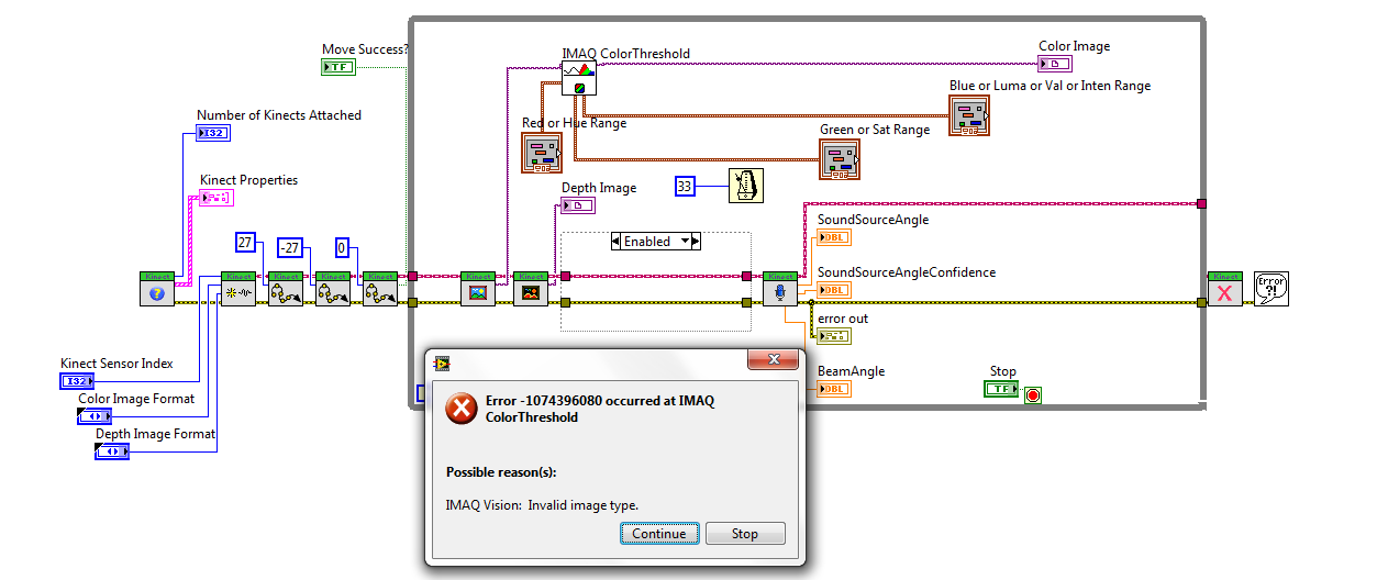
Any suggestions on how to fix it?
Thanks.
- Mark as Read
- Mark as New
- Bookmark
- Permalink
- Report to a Moderator
This is, unfortunately, a fairly generic error. It usually means that the image type which is required by the function is not the type provided. The color image threshold requires, obviously, a color image. If I recall, the depth image is actually a grayscale image which is being drawn using colors instead of gray (although I may be wrong). If that's the case, use the normal threshold function (not color) and it should work. Between the standard threshold function and the color threshold, you should be able to convert any image to binary.
- Mark as Read
- Mark as New
- Bookmark
- Permalink
- Report to a Moderator
I tried using the regular threshold but that gives the same error. It says in the front panel that the video output for the color image is 32 bit RGB, but when I apply the color threshold, it changes it to an 8 bit image. Could the issue be that the color display only works if it's a 32 bit RGB being displayed? If so, how can I get around that? Thanks.
- Mark as Read
- Mark as New
- Bookmark
- Permalink
- Report to a Moderator
I would follow this procedure to narrow the error:
1. Probe the error wires (right click and Probe) at each step in your process. Narrow down the source of the error to a specific vision block (there should be no error going into it, and an error coming out). Is that still an Invalid Image Type Error?
2. Probe the image wire going into the block you've found is producing the error. Why type is it?
3. Check your destination image. Is it of a type that the image processing block produces?
4. Now that you know your types and what block is failing, consult the labview help for that block. CTRL+H gets you the context help. Hover over the block in question and click Detailed Help in the dialog which desribes the input and output to the function (the context help dialog). This detailed help shows valid input types at the top of the page. Confirm, based on your previous tests, that the type is expected.
As I said previously, between color image threshold and threshold, you can perform that operation on any image type IMAQ supports. That error can actually be generated in conditions other than an invalid image type so be sure you understand where the first error is happening. If, for instance, there was an error with another input parameter in an earlier function, that error could cascade to the next function and give a weird error (simiarly to how visual studios and other compiles show non-sense errors when there's a gross syntactic mistake).
