Triangle Wave Generated PWM
- Subscribe to RSS Feed
- Mark as New
- Mark as Read
- Bookmark
- Subscribe
- Printer Friendly Page
- Report to a Moderator
Products and Environment
This section reflects the products and operating system used to create the example.To download NI software, including the products shown below, visit ni.com/downloads.
- LabVIEW
Software
- NI RIO
Driver
Code and Documents
Attachment
Overview
This component of code shows how to use a sawtooth to generate a PWM signal. The example compares a sinewave to a triangle waveform. The PWM signal generated is the output of the comparator.
Description
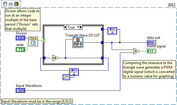
This code has been designed to run in a single-cycle timed loop, but also contains a clock deriver that allows the code to run at an integer fraction of the base clock frequency (defined by the "Divisor" control). There is also a boolean to reset the clock deriver. The following images shows an example of the PWM generator being used with a 5kHz sinewave as well as the block diagram to go with it. The attached files include the PWM generator block itself as well as an example of its use in a single-cycle timed loop.
If a DC signal is fed to the comparator, the output is a PWM signal with a constant duty cycle that is equal to the ratio of the DC signal to the peak value of the triangle wave. If some other analog waveform is sent to the comparator, the PWM output varies to correspond to the analog waveform.
This code could be extended to a different version of a PWM generator by replacing the triangle wave with various versions of a sawtooth look-up table.
NOTE: the test code in "TriangleWavePWMGen test.vi" is to demonstrate the behavior of the block on a Windows-based system. It won't directly compile to FPGA without some changes. However, the code in "simple FPGA test.vi" will compile and will generate an indicator that cycles through the PWM range at 0.5Hz.
Steps to Execute Code
LabVIEW Development Environment
- Open the TrianglePWM.lvproj file
- Open the TriangleWavePWMGenTest.vi
- Run the VI
- Notice that the correct PWM wave being generated from the two signals on the top plot.
LabVIEW FPGA
- Update the FPGA target to match your configuration
- Compile and run the Simple FPGA Test.vi
Requirements
LabVIEW 2010 FPGA Module "or compatible"
VI Snippet
Additional Information or References
**This document has been updated to meet the current required format for the NI Code Exchange. For more details visit this discussion thread**
Example code from the Example Code Exchange in the NI Community is licensed with the MIT license.
- Mark as Read
- Mark as New
- Bookmark
- Permalink
- Report to a Moderator
I have placed the sample code above in a project for the PXI-7831R. A compiler error is generated. Internally pipelined object(s) not connected to a feedback node. The error points to the "Look-Up Table 1D 'Triangle Wave 1D LUT'".
What is purpose of the inital value of 275 on the feedback node for the index count into the Triangle Wave table?
LabView 2009 SP1
- Mark as Read
- Mark as New
- Bookmark
- Permalink
- Report to a Moderator
The short answer is that the test code posted above was designed to be compiled to FPGA. I wanted a test that demonstrated a graph of the output, but graph indicators are not good programming practice for FPGA code.
I'll add a piece of test code that you can compile easily to FPGA. The output should be an indicator that fades in and out at 2 Hz.
The initialization of 275 was to start the triangle wave in the middle of its range.
I hope that helps.
- Mark as Read
- Mark as New
- Bookmark
- Permalink
- Report to a Moderator
Thanks for updating the example. I used this as a basis for a ramp PWM. I now have it working on the PXI-7831R. I have implemented variable limiting on the PWM output (minimum and maximum ON time (clock ticks)) and variable Dead Time Delay (ticks). It's hard to believe all this code executes in a SCTL.
- Mark as Read
- Mark as New
- Bookmark
- Permalink
- Report to a Moderator
You can find alternative sine-triangle PWM code which offers 16-bit resolution on a fixed point modulation index and supports overmodulation as part of the Power Electronics Design Guide code, which you can download from here:
Download Power Electronics Design Guide code
- Mark as Read
- Mark as New
- Bookmark
- Permalink
- Report to a Moderator
Hi, I am having trouble using these files to generate a PWM output signal that is accurate beyond 10 kHz frequency. In order to increase the frequency of the output, I have found that I have to reduce the number of elements in the look up table and this has decreased the accuracy of the output. For example, when I input a constant DC waveform of 1/2 the final value of the triangle wave, the pwm output is about .4 duty cycle.
How do I make this system accurate for higher frequency triangle waves?
- Mark as Read
- Mark as New
- Bookmark
- Permalink
- Report to a Moderator
how can I get the file "trianglewavepwm gen test.vi" to compile to an FPGA and maintain the sine and triangle waveforms? I replaced the single time loop with a while loop and added an I/O node and am getting an entirely different PWM output.
- Mark as Read
- Mark as New
- Bookmark
- Permalink
- Report to a Moderator
Have you find the answer?
