Sending Commands Over Reflective Memory Modules Using Network Interrupts
- Subscribe to RSS Feed
- Mark as New
- Mark as Read
- Bookmark
- Subscribe
- Printer Friendly Page
- Report to a Moderator
Code and Documents
Attachment
Overview
The GE cPCI-5565PIORC reflective memory modules are able to provide high-speed, low-latency, deterministic data sharing between many systems. The network works by copying memory stored on one device to every device on the network. Specifically, data writes are stored in local SDRAM and sent over the fiber-optic cable to the other nodes on the network.
There are two interrupts modes available on Reflective Memory nodes:DMA Interrupts and Network Interrupts. The DMA Interrupt is used to notify the host of a completed reflective memory write. The network interrupt is used to send interrupts over the fiber optic network. Network interrupts are ideal for sending low-latency command or event information. This example provides an example of network interrupt command communication over a reflective memory network.
Description
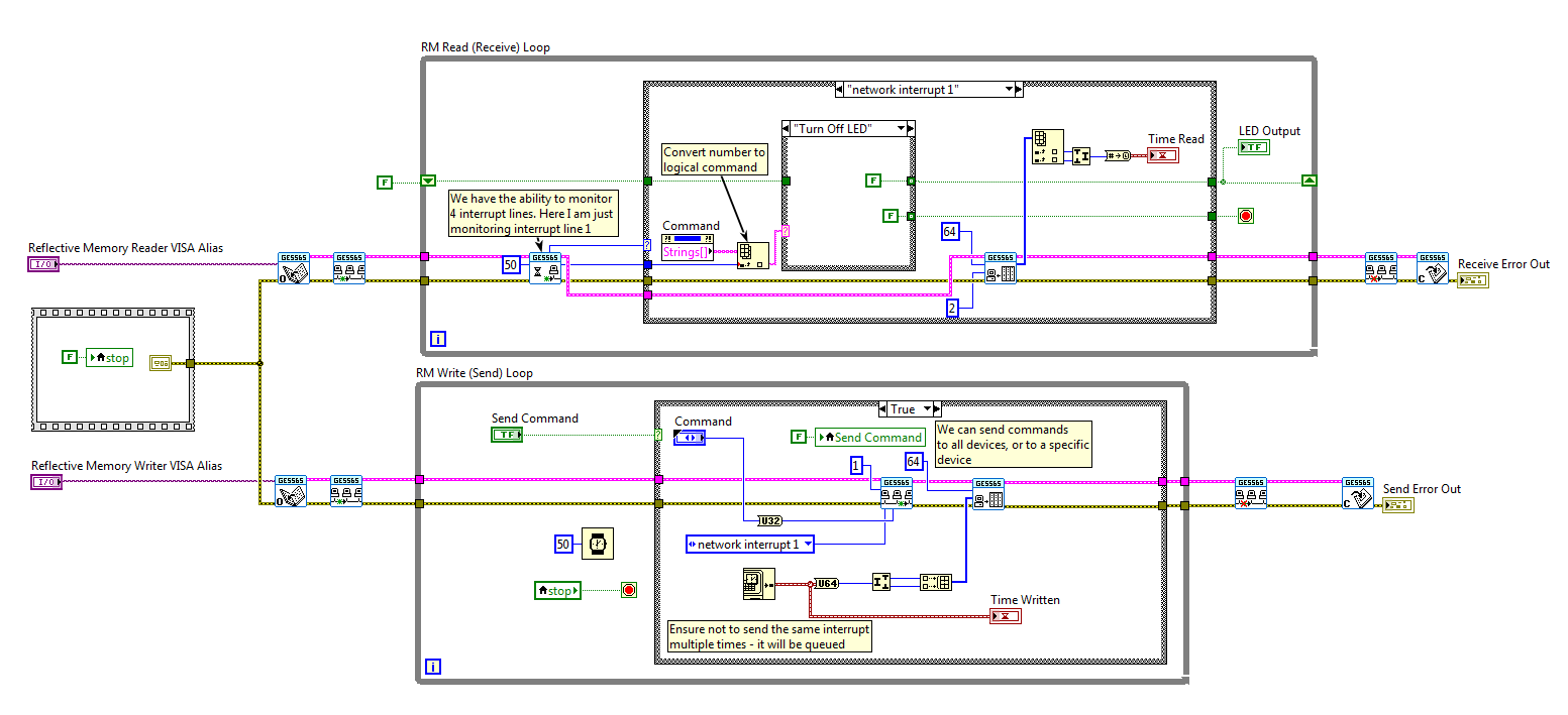
The example is written for a single PXI chassis with two reflective memory modules. This example can be extended to multiple PXI chasses by separating the read and write loops and executing them on separate chasses.
The user is able to select from a number of commands: Turn on LED, Turn off LED, and Stop. Once a command is selected, the user clicks the Send Command button to send the network interrupt. The example uses network interrupt line 1 (there are 4 to chose from), and sends the interrupt directly to device 1. The device number is set in hardware. Information on the procedure to set the device number can be found in the 5565 manual. The reader reflective memory card continually polls the network for an event using the Wait for Event VI. Once an interrupt is detected, the read loop decodes the command back to a String representation of the command, and executes the desired action. An additional feature is that the example writes the time that the network interrupt was sent to a reflective memory address, and when the network interrupt is received, the time is read back. This could be extended to benchmark the time difference between the writes and reads.
Steps to Implement or Execute Code
Note: The instrument driver can also be installed to the LabVIEW 2014 directory. The example has been tested on LabVIEW 2014 and 2013.
- Download the 2013 GE 5565 PIORC Instrument Driver.
- Install the driver by extracting the driver files to <Program Files>/National Instruments/LabVIEW 2013/instr.lib.
- Install the Network Interrupt INF Device Driver file. Open the INF file for directions. Please note that having both the GE5565_DMA_Interrupts.inf and GE5565_NetworkInterrupts.inf files installed may cause the example not to function.
- Reboot the PXI system to complete the Network Interrupt INF Device Driver file install.
- Open the attached example.
- Add your RT PXI chassis to the project and move the Network Interrupt.vi and Command Type Defintiion.ctl to your target.
- Navigate to MAX to obtain the Reflective Memory module aliases.
- Open the Network Interrupts.vi example.
- Select the visa aliases in the example front panel.
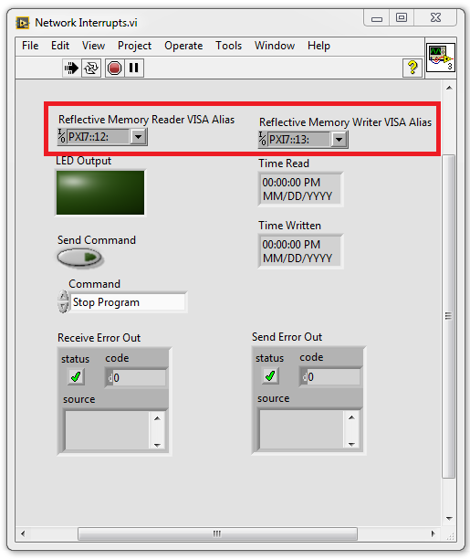
- Run the program. Select a command from the Command control and press the Send command to see the result.
Requirements
Software
LabVIEW 2013/4
GE 5565 PIORC Instrument Driver
Hardware
RT PXI System
2 x PXI GE 5565 PIORC Modules
Additional Images or Video
Systems Engineer, Embedded Systems
Certified LabVIEW Architect, Certified LabVIEW Embedded Systems Developer
National Instruments
Example code from the Example Code Exchange in the NI Community is licensed with the MIT license.
- Mark as Read
- Mark as New
- Bookmark
- Permalink
- Report to a Moderator
