Description
Description-Separate-1Overview
This example allows you to load a 3D model (4 models are provided), place sensors on the model and map simulated sensor data to the model.
Description
New way to visualize acquired and simulated data in your VIs: 3D sensor mapping. Using a basic Express VI, you can import a 3D CAD model, assign sensors, and map DAQ channel data directly onto the model. This example illustrates how to use this feature.
Requirements: LabVIEW 2012 (or compatible).
Steps to Implement or Execute Code:
- Run the VI. By default the VI will use automatically simulated data
- Press the LED to toggle between automatically generated values and input values from the sliders on the left of the 3D picture control
- Navigate to the block diagram and double click on the Sensor Mapping Express VI to open its dialog window.
- Left click anywhere in the window and drag the cursor to rotate the model.
- Hold the Shift key, left click, and drag the cursor to zoom in and out.
- Hold the Ctrl key, left click and drag to move the model to a new position in the window.
Additional Information or References:
 3D Sensor Mapping Example FP.png
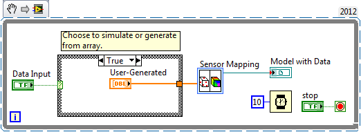 3D Sensor Mapping Example sn.png
**This document has been updated to meet the current required format for the NI Code Exchange.**
Description-Separate-2
Todd S.
LabVIEW Community Manager
National Instruments


