- Document History
- Subscribe to RSS Feed
- Mark as New
- Mark as Read
- Bookmark
- Subscribe
- Printer Friendly Page
- Report to a Moderator
- Subscribe to RSS Feed
- Mark as New
- Mark as Read
- Bookmark
- Subscribe
- Printer Friendly Page
- Report to a Moderator
Measurement control system for biomass gas engines
University and Department: The University of Tokyo, School of Engineering, Department of Mechanical Engineering
Team Members: Go Tomatsu
Faculty Advisors: Shigehiko Kaneko
Primary Email Address: kaneko@mech.t.u-tokyo.ac.jp
Primary Telephone Number: 81-3-5802-2946
Project Information
Parts used to design and complete project:
PXI-8176
PXI-6071E
PXI-6733
PXI-6602
LabVIEW
1. Background
In recent years, in light of various environmental and energy issues, the utilization of biomass resources is being encouraged. This study describes the development of biomass gas engines as a way to utilize biomass resources.
Biomass gas is generated from fermentation or pyrolysis of organic matter, and is a mixture of combustible gases such as methane (CH4), hydrogen (H2) and carbon monoxide (CO) and non-combustible gases such as carbon dioxide (CO2) and nitrogen (N2). The mixture ratios of the gases vary depending on the types of biomass resources used and on the gasification method. Ratios also change by the minute, depending on variables such as the gasification furnace temperature. Since biomass gas contains large volumes of low calorific gases (H2, CO) and non-flammable gases (CO2, N2) that are not generally used as fuel, it has low calorific value compared to city gas. Such characteristics cause problems in operating an engine.
To develop an engine compatible with biomass gas fuel, it is necessary to have an accurate understanding of the effects of fuel calorific values and differences in fuel gas compositions on the engine. As the first phase of biomass gas engine development, this study analyzes the combustion characteristics of simulated biomass gas fuels, by operating the engine with various mixtures of gas compositions.
2. Issues
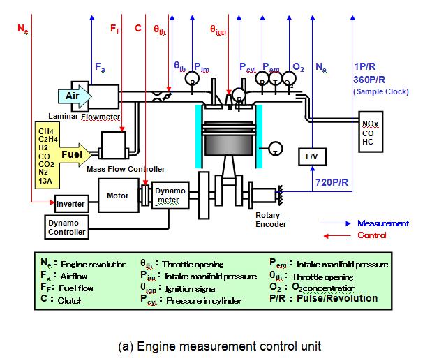
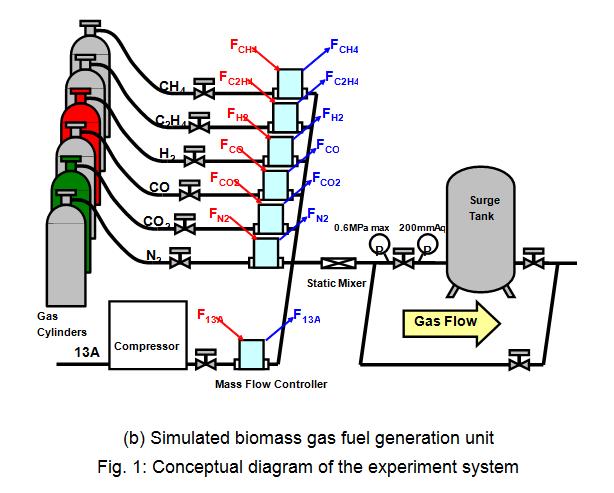
First, Figure 1 (a) shows the conceptual diagram of the engine measurement control unit used in the experiment and Figure 1 (b) is the conceptual diagram of the simulated biomass gas fuel generation unit. In the engine operation experiment, the simulated biomass gas fuel from the simulated biomass gas fuel generation unit is supplied to the engine, and the engine operation data are measured for each simulated biomass gas fuel.
The two main issues in engine operation experiments using these systems are the synchronization of measurement signals and the efficiency in operating the equipments during the experiment. Below, the details of the issues are categorized according to measurement, engine operation control and simulated biomass generation.
<Measurement>
To analyze and evaluate the effects that differences in fuel gas compositions have on engine operation, various data during engine operation such as fuel flow, airflow, temperatures of various engine parts and pressure are measured. For future analyses, it is desirable that measurement is synchronized with the engine crank motion. Sampling rates should be set flexibly, for example, rapidly changing signals such as pressure should be sampled for each crank angle (9000 Hz at the rated engine revolution of 1500 rpm) while slow-changing signals such as temperature should be sampled for each crank revolution. Since the output voltage range varies depending on the sensor amplifier, it is desirable to set the range for each channel to obtain accurate measurements.
<Engine operation control>
When an engine is started, the clutch needs to be engaged, the cell motor rotated, and the clutch disengaged once the fuel is supplied. Also, during operation, it is necessary to adjust airflow, fuel flow and ignition timing to the predetermined experiment conditions by operating the actuators such as the throttle, mass flow controller and spark plug. Operating multiple devices while monitoring the engine operation during the experiment places a heavy burden on the testers, and improvements in efficiency are desired.
<Generation of simulated biomass gas>
Simulated biomass gas fuel is generated in mixtures of arbitrary ratios by independently monitoring and controlling six types of gases in canisters (CH4, C2H4, H2, CO, CO2, N2) and city gas 13A with seven mass flow controllers. Controlling the seven units simultaneously is complicated.
3. Solution
3-1. System configuration
To solve this problem, the I/Os of the engine measurement unit and the simulated biomass gas fuel generation unit were built as NI-based systems, establishing an engine measurement control system and a simulated biomass gas fuel generation system. In both cases, LabVIEW was used to develop the software.
For the engine measurement control system, the PXI-controller (PXI-8176), A/D board PXI-6071E, D/A board PXI-6733 and counter board PXI-6602 were used. For measurement, the sensor output data are sampled per crank angle using the A/D board PXI-6071E, based on the signal from the rotary encoder. For operation control, actuators such as the clutch, cell motor, throttle and mass flow controller are operated using the D/A board PXI-6733, and ignition signals are generated using the counter board PXI-6602. So NI products were used for the I/O signals of all devices operated during the engine operation, allowing the engine operation and measurement to be controlled via a PC.
For the simulated biomass gas generation system, an off-the-shelf desktop PC, the PXI-chassis, A/D board PXI-6031E and D/A board PXI-6733 were used. The flow rate of each gas composition is controlled with the voltage output from the D/A board PXI-6733, and the actual flow rate is measured with the A/D board. The system enabled the simultaneous operation of seven mass flow controllers with a PC, which made it possible to control the mixture ratios of seven gas compositions (13A, CH4, C2H4, H2, CO, CO2 and N2).
3-2. Result
As for measurements, sampling was synchronized with the engine crank motion. Also, sampling rates for each channel and measurement ranges can be easily set with the software. As for operation of the units during the experiment, all required operations are now controllable via a PC, greatly reducing the testers' burden. So all issues faced in establishing the system were resolved.
LabVIEW was also used to analyze the measurement data. So regarding software, one only needs to learn LabVIEW to conduct all operations from experiment to analysis. Since it was not necessary to learn multiple programming languages, the time required was reduced.
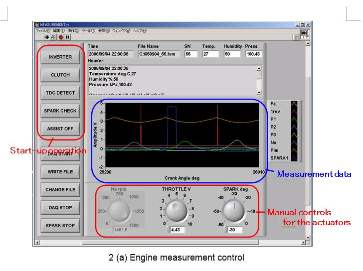
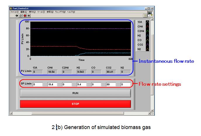
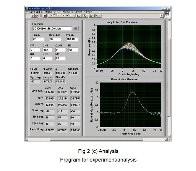
Fig. 2 shows the front panel of the program used for the experiment and analysis. Fig. 2 (a) is the engine measurement control program that measures the engine operation data, after the engine start-up sequence is conducted automatically and actuators are controlled manually to the experiment conditions. Fig. 2 (b) is the front panel of the program that sets the simulated biomass gas fuel mixture ratio. The flow rates of seven gases can be set and monitored individually. The measured data are analyzed for engine performance (output, thermal efficiency and variation coefficient of the output) and combustion characteristics (combustion start time and combustion period) with the analysis program in Fig. 2 (c).
Experiments and analyses are currently being conducted with this measurement/analysis system.
4. Conclusion
Using LabVIEW, a measurement control system for biomass gas engines was established. The desired system was achieved with software that provided flexible settings and operations to control multiple I/O signals, reducing the burden during experiments. Also, the ability to use LabVIEW from measurement to analysis allowed for improvements in efficiency.
Lastly, in the future, the system that was established can be used to prototype the engine control units for biomass gas fuel with only changes to the software, so further improvements to development efficiency can be expected.
