- Subscribe to RSS Feed
- Mark Topic as New
- Mark Topic as Read
- Float this Topic for Current User
- Bookmark
- Subscribe
- Mute
- Printer Friendly Page
myRIO Balancing Robot - Prototype
08-09-2013 07:14 AM
- Mark as New
- Bookmark
- Subscribe
- Mute
- Subscribe to RSS Feed
- Permalink
- Report to a Moderator
 | This document was created for the myRIO Balancing Robot Project https://decibel.ni.com/content/groups/myrio-balancing-robot |  |
Prototype Development
Start Balancing, Fast!
Overview
This document describes the prototype development for myRIO Balancing Robot that took place at NI Switzerland in the time between Start of Sprint 1 (22.07.2013) until the End of Sprint 8 (11.10.2013).
The prototype will be the departing points for Student Projects in Autumn 2013.
Table of Contents
1. General Description
The aim of this prototype was to quickly start balancing.
Indeed, two weeks after the delivery, myBOT was able to stand, drive and turn around his axe.
1. Hardware Implementation
In the following, all activities around the development of the prototype are listed, all User Stories corresponding to this development are presented here with their outcome.
U-002: CAD Prototype
At the beginning a CAD Prototype was created.
The CAD Prototype for the myRIO Balancing Robot Prototype is described in https://decibel.ni.com/content/docs/DOC-30640
U-011: Define Parts
The Parts for myRIO Balancing Robot Prototype have been defined and ordered at Digilent. All parts can be found here: https://www.digilentinc.com
The following table lists all elements necessary to build your own Balancing Robot Prototype (the myRIO itself is not listed..)
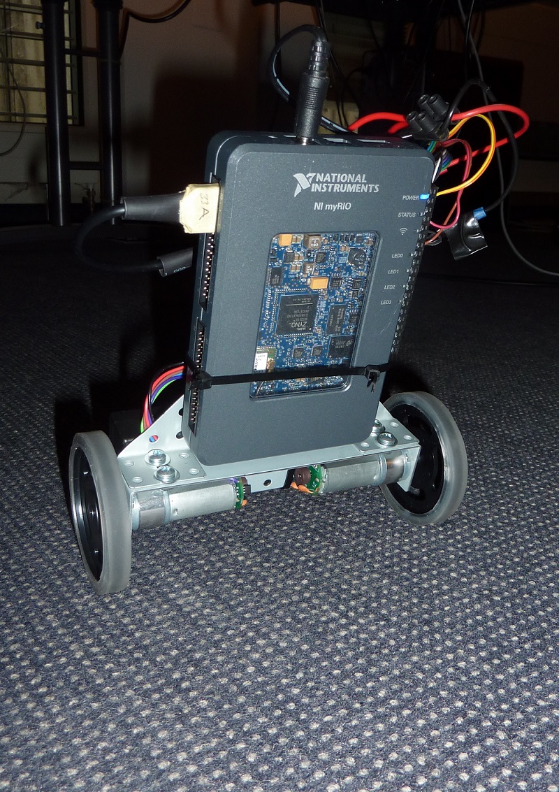
U-012: Build Prototype
 klein.jpg)
 klein.jpg)
 klein.jpg)
 klein.jpg)
 klein.jpg)
 klein.jpg)
 klein.jpg)
 klein.jpg)
 klein.jpg)
 klein.jpg)
 klein.jpg)
 klein.jpg)
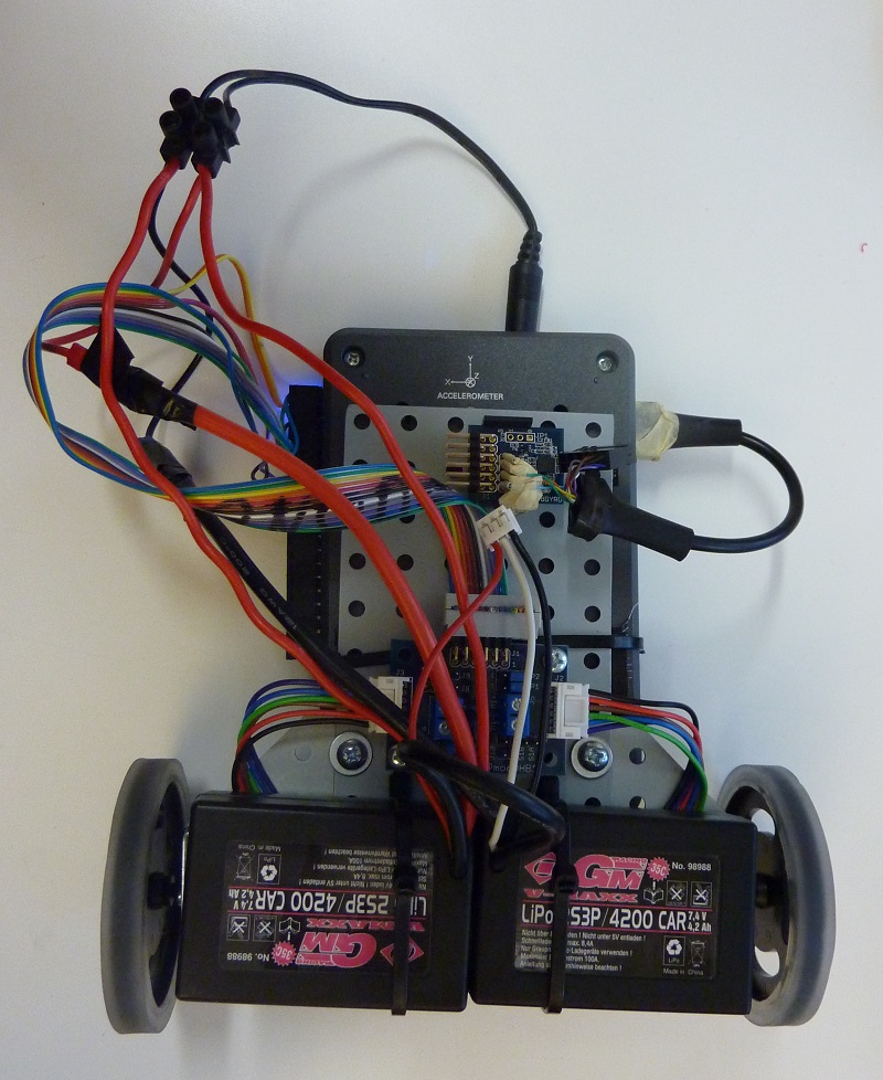
U-021: Electronics
Thanks to the choice of the Digilent Pmod Sensors and H-Bridge, no additional PCB is required for the myRIO Balancing Robot.
The only thing that must have been defined in U-021 was therefore the choice of the battery for the final version.
Tests have been made about the Power consumption of the motors and the myRIO.
It turned out, that the myRIO needs about 5W, the motors need between some and over 10 W (depending on the action)
A long time test with an Battery Pack (7.4V, 4200mAh, 31.08Wh) showed that the Prototype was running over 5h without the battery being totally empty. This means, the total system took around 6W.
For the final prototype a Battery of 11.1V, 1300mAh, 14.43Wh has been chosen. The estimate is, that the myBOT can run on this battery for 2-3h.
2. Software
The full LV project is attached.
SubVIs
Most functions have been encapsuled in SubVIs. They're built upon a SubVI Template.
[Picture]
Controller
For the prototype several controller options have been tested.
1) PI-Controller based on the angle
2) PD-Controller based on angle and angular velocity as described here. http://www.chrismarion.net/index.php?option=com_content&view=article&id=122:the-segway-theory&catid=...
Sensors
For the prototype sensor fusion has been use to estimate the angle of the robot. This has been done using a complementary filter as described here: http://www.chrismarion.net/index.php?option=com_content&view=article&id=122:the-segway-theory&catid=...https://docs.google.com/viewer?url=http://web.mit.edu/scolton/www/filter.pdf
Drive Controller
After the robot was able to balance a drive controller proof of concept was implemented (quick and dirty) to see if the idea could work out.
The drive controller works as follows:
- To drive straight, the Controller increases an angle offset on the body's angle. This leads to an inclination in the bodys angle and therefore the robot needs to drive in this direction in order to not eat dust.
- To drive round, the Controller sets an offset in the encoder value of the left and the right wheel. This leads to the robot turning in circles.
3. Conclusion
The prototype fullfills it's purpose. It serves as a starting point for Subprojects.
5. Sources
6. Further Information
