- Subscribe to RSS Feed
- Mark Topic as New
- Mark Topic as Read
- Float this Topic for Current User
- Bookmark
- Subscribe
- Mute
- Printer Friendly Page
Event Structure kills my main while loop
10-01-2007 05:15 AM
- Mark as New
- Bookmark
- Subscribe
- Mute
- Subscribe to RSS Feed
- Permalink
- Report to a Moderator
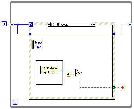
Until I press the Start button, the program just reads a voltage from an analog input. This works fine. When I press the Start button I want the program to do some things until the voltage read from the analog input reaches a certain level (in the screenshot of a simplified program attached below this level (pressure) is set to 4 volts). So this simple program should, when I press the Start button, wait for the voltage to reach 4 volts and then display a dialog box with "The process completed successfully".
My problem is that as soon as I press the Start button the main while loop no longer reads from the analog input and therefore never finds out when the voltage goes above 4 volts.
The program freezes and can't even be stopped via the Stop button but has to be stopped the nasty way by presseing the "Abort Execution" button on the tool bar.
How do I create an Event Structure that does not ignore the main while loop?
I have no code in the "Timeout" case of the Event Structure.
Any help or pointers would be greatly appreciated.
Regards,
Claus
10-01-2007 06:12 AM
- Mark as New
- Bookmark
- Subscribe
- Mute
- Subscribe to RSS Feed
- Permalink
- Report to a Moderator
10-01-2007 06:15 AM - edited 10-01-2007 06:15 AM
- Mark as New
- Bookmark
- Subscribe
- Mute
- Subscribe to RSS Feed
- Permalink
- Report to a Moderator
Message Edited by Stradis on 10-01-2007 07:17 AM
Paul
10-01-2007 06:18 AM
- Mark as New
- Bookmark
- Subscribe
- Mute
- Subscribe to RSS Feed
- Permalink
- Report to a Moderator
Hai!
I also came across such kind of problems earlier, see i prefer that have two timed while loop one will work independently and acquire your signal, in the second loop do your execution loop soon that your event structure will execute your sequence. try this it will work definitely.
10-01-2007 07:03 AM
- Mark as New
- Bookmark
- Subscribe
- Mute
- Subscribe to RSS Feed
- Permalink
- Report to a Moderator
I tried to make the program structure you recommended. I put my data acq. as the Timeout event. But when I start my program, it does not read from the analog in (i.e. it does not execute the code inside the Timeout case). I thought the code inside the Timeout case would execute as soon as you start the VI and until the start or stop button is pressed?
However, if I press the start button, it executes the code in the Start case and then returns and executes code in the Timeout case.
What I would really like to do, is start execute the Timeout case immediately after I start the VI, without pressing the Start button. In the final program it would mean trouble if you would have to run the Start case before you can run the Timeout case.
Best regards,
Claus
10-01-2007 07:09 AM - edited 10-01-2007 07:09 AM
- Mark as New
- Bookmark
- Subscribe
- Mute
- Subscribe to RSS Feed
- Permalink
- Report to a Moderator
This approach with two seperate while loops also makes sense to me. I need to constantly monitor the analog input (and also control an analog output). Separating the analog input/output routines from the user interaction routines might make the program more logic. I will give it a try.
Regards,
Claus
Message Edited by Claus_DK on 10-01-2007 07:11 AM
10-01-2007 07:12 AM - edited 10-01-2007 07:12 AM
- Mark as New
- Bookmark
- Subscribe
- Mute
- Subscribe to RSS Feed
- Permalink
- Report to a Moderator
Message Edited by Stradis on 10-01-2007 08:13 AM
many ways to achieve this. I would only recommend a two loop solution IF other things need to be processed (IE user input response) or if timing is crutial in the data acquistion. You could remove the shift register, and then 'AND' the start boolean with the evaluation of the data acquistion
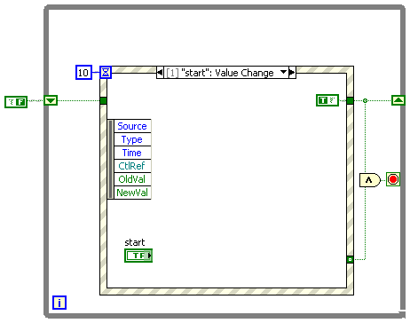
Message Edited by Stradis on 10-01-2007 08:15 AM
Paul
10-01-2007 08:11 AM
- Mark as New
- Bookmark
- Subscribe
- Mute
- Subscribe to RSS Feed
- Permalink
- Report to a Moderator
@Claus_DK wrote:
Claus,
You already received quite a bit of good advice, but there are quite a few misconceptions about dataflow that you seem to have and now is a good time to clear them up. Often it is most illustrative to run your VI in "execution highlighting mode" to see what is happening under the hood. Try it!
Here are a few points:
- You 1 ms wait is pointless, because the loop time is entirely determined by the 10ms timeout (or the acquisition, whatever takes longest). Since there is no data dependency, the 1ms wait will start togehter with the event struture and teh DAQ part, but will finish first.
- Since the loop always spins with a 10ms period, there is no need to have the inner while loop. You don't even need the even structure.
- All you need is the main loop with your DAQ part and a comparison of the position with 4 connected directly. Now hook up a LED (or a case structure containing your popup) to the comparison and have the LED light up (or popup fired) when the comparison is TRUE.
- Typically, a popup dialog is not that great, because it requires operator assistance and will stall the entire program until it is OKd.
- You don't need it anyway, but your inner while loop does not have a wait statement and thus will spin millions of times per second, mostly reading the same old value over and over again and starving all other processes for CPU. Since you seem to only intend to read new values every 10ms it seems silly to check much more often. This is like the kid constantly asking "are we there yet".
- Right now you don't specify what you happen with the DAQ after the level has been reached. Should it just continue measuring?
- Unless something else is being started, the start button has no real purpose because the condition will be reached no matter if you press it or not. Why do you even need to press it?
- I am not sure where you got those subVIs, but it seems to have some input connectors on the right side. This should be avoided for clarity.
- Notice all these corecion dots? It helps to make the diagram constants the correct representation the subVI expects.
10-01-2007 08:46 AM
- Mark as New
- Bookmark
- Subscribe
- Mute
- Subscribe to RSS Feed
- Permalink
- Report to a Moderator
Since this program is just a simplified versoin of what I really want to do, I will give a few more details and try to answer your questions.
1. Yes you are absolutely right. I put the 1 ms delay in the original program to see if this iteration speed would suffice for what I need to do. In this simple "demo program" it is useless.
2. In this while loop I omitted the analog output. I need a certain output voltage level until the Position sensor reaches a certain level (in this case I chose 4 randomly). After this I have other steps: The output voltage shold remain 0 volts for a certain period of time, then the output voltage has to be the same as before the holding time but with opposite polarity until another position is reached and finally the voltage is set to 0 and the dialog box is showed.
3. Since I need a sequence of things to happen as described above, I don't see how I can avoid a sequence inside a while loop.
4. In this case I find it OK since it indicates the completion of a process and since nothing is going to happen afterwards.
5. The position sensor is detecting the position of a piston controlled by a motor. I need to position this piston very accurately so I need to read the position often. The voltage output that I mentioned above is controlling this motor. I don't know yet, but maybe I will even have to decrease the voltage to the motor as the piston approaches its intended position to approach this position slowly and thereby accurately enough.
6. It runs the sequence described in point 2.
7. The start button is starting the sequence described in point 2. When the sequence isn't running, manual positioning of the motor (i.e. manual control of the output voltage has to be enabled). For this reason I planned to let the position sensor run continously.
8. The subVIs are from Measurement Computing and are controlling the USB based analog inputs and outputs. Actually the input is not on the right side. I manually put the connection od the right side, because of the limited space on the left side. But I promise to do a "Clean up wire" immediately in order to follow standard procedures 🙂
9. I am not familiar with the corecion dots or how the are helpful. Or did you by any chance mean correction dots (not that I know anything about those either)? I will have to look into that.
Thank you again for taking time to give me such thorough feedback.
Claus
10-02-2007 10:58 AM
- Mark as New
- Bookmark
- Subscribe
- Mute
- Subscribe to RSS Feed
- Permalink
- Report to a Moderator
Claus_DK wrote:
2. In this while loop I omitted the analog output. I need a certain output voltage level until the Position sensor reaches a certain level (in this case I chose 4 randomly). After this I have other steps: The output voltage shold remain 0 volts for a certain period of time, then the output voltage has to be the same as before the holding time but with opposite polarity until another position is reached and finally the voltage is set to 0 and the dialog box is showed.
3. Since I need a sequence of things to happen as described above, I don't see how I can avoid a sequence inside a while loop.You don't need all this. No inner while loop, no sequence structure and no event structure. You can design the entire thing as a state machine using the outer while loop. Since you are spinning the loop anyway, you don't need an events structure at all, just poll the button and change states if indicated.
4. In this case I find it OK since it indicates the completion of a process and since nothing is going to happen afterwards.
Life always goes on, something will always happen afterwards, even it is just stopping the program or entering a wait state. (or going to dinner 😄 ).
5. The position sensor is detecting the position of a piston controlled by a motor. I need to position this piston very accurately so I need to read the position often. The voltage output that I mentioned above is controlling this motor. I don't know yet, but maybe I will even have to decrease the voltage to the motor as the piston approaches its intended position to approach this position slowly and thereby accurately enough.
You can use a 1ms delay. If your timing requirements need to be more precise, you need to use LabVIEW RT and the code does not belong on a plain OS.
6. It runs the sequence described in point 2.
7. The start button is starting the sequence described in point 2. When the sequence isn't running, manual positioning of the motor (i.e. manual control of the output voltage has to be enabled). For this reason I planned to let the position sensor run continously.See above.
8. The subVIs are from Measurement Computing and are controlling the USB based analog inputs and outputs. Actually the input is not on the right side. I manually put the connection od the right side, because of the limited space on the left side. But I promise to do a "Clean up wire" immediately in order to follow standard procedures 🙂
9. I am not familiar with the corecion dots or how the are helpful. Or did you by any chance mean correction dots (not that I know anything about those either)? I will have to look into that.A coercion dot (red) shows whenever the input to a function or subVI does not match the data representation that the function expects. (trher are no correction dots in LabVIEW).
