- Document History
- Subscribe to RSS Feed
- Mark as New
- Mark as Read
- Bookmark
- Subscribe
- Printer Friendly Page
- Report to a Moderator
- Subscribe to RSS Feed
- Mark as New
- Mark as Read
- Bookmark
- Subscribe
- Printer Friendly Page
- Report to a Moderator
Walkie Talkie with NI USRP-RIO and LabVIEW
Introduction:
This example can turn two USRP-RIO stations, into a pair of walkie-talkie systems i.e.a packet transmitter and receiver communicating audio. The Tx and Rx algorithms are implemented using basic LabVIEW VIs (not using Modulation Toolkit). It can be used as a reference to build a digital communication system from ground up.
Hardware required:
- 1 or 2 USRP RIOs
- 1 or 2 Laptops/Desktops with PCIe connectivity accessories to the USRP RIO
- 2 Antennas, chosen according to the carrier frequency to be used.
Software required (with the versions used to create the project) :
- LabVIEW 2015
- NI-USRP 15.0
- Modulation Toolkit 4.1
Project Contents:
This example is created from the NI-USRP Simple Streaming project template. All the contents of the template are kept intact, and new VIs are created for the walkie-talkie. The Auto-populating folder Audio Packet Xcvr Main contains all the top-level VIs
- Audio Packet Xcvr Simulator - Software loop-back for debugging
- Audio Packet Xcvr USRP RIO debug - Main VI with Waveform Graphs for debugging
- Audio Packet Xcvr USRP RIO - Main VI
The Auto-populating folder Audio Packet Xcvr subVIs contains all the subVIs used.
Instructions to run:
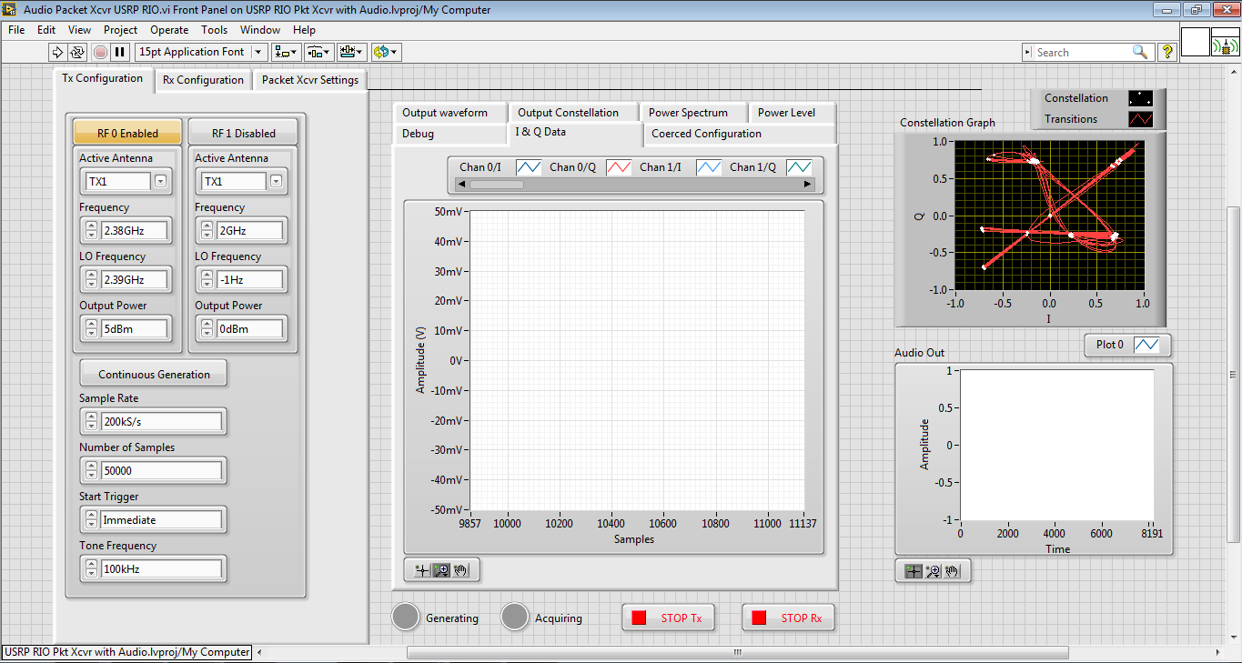
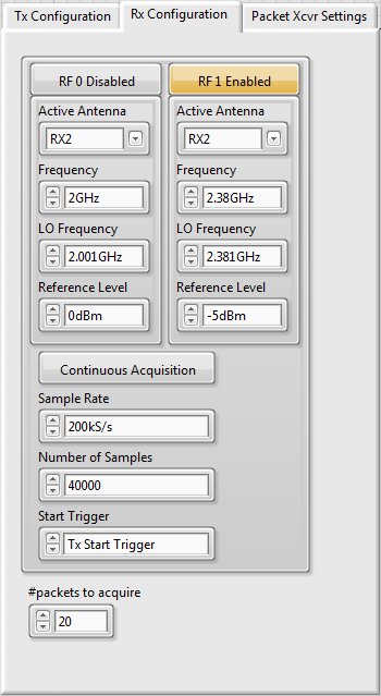
The default settings implement a loop back between RF0/TX1 and RF1/RX2 on the same USRP RIO. To setup communication between two USRP RIOs, the Tx and Rx frequencies need to be set appropriately.
The LO Frequency and Frequency controls are set to differ by 10MHz, so that the LO is shifted out of the band under use. This removes the effect of LO leakage.
Note : Although all the settings are user changeable, it does not mean the code works with any value. For example, as we keep increasing the sampling rate of Audio and IQ, the processing power needed increases, and the streaming could begin to timeout. The default settings are however, tested with thoroughly.
Top level VI:
- Mic and Modulation Loop: Acquire samples from the connected microphone, converts to a bit packets, adds training sequence, and generates the modulated IQ data
- Tx Loop: Transfers IQ data to the USRP RIO, for generation
- Rx Loop: Acquires IQ data from the USRP RIO, implements the receiver algorithm including packet detection, Pulse shaping, Frame detection, CFO correction, Phase offset correction and generates audio data.
- Speaker Loop: Generates the audio through the connected speaker.
All the subVIs used are documented. The default FPGA VI is used as it is.
- Mark as Read
- Mark as New
- Bookmark
- Permalink
- Report to a Moderator
Hello
Sorry, I want to know
How could I use this vi but using usrp 2920?
or
Do you have any examples tx and Rx of digital audio using the usrp2920?
I want to make the same application that you created but using usrp 2920.
I tried several things but I can not do it.
Thanks for the help
- Mark as Read
- Mark as New
- Bookmark
- Permalink
- Report to a Moderator
Hello, i just bought the bord USRP2920 With PXIE 8880,and i am tring to using to communicate with RF, can you help with some VI.
I work with RF and wanna using this board
RF = Radio Frequency.
- Mark as Read
- Mark as New
- Bookmark
- Permalink
- Report to a Moderator
hello
many thanks for that Example but could you offer a sample program working with NI USRP 2920 as mentioned before i the Comments
Appreciate your kindly help ....
@Varun_Tripuraneni wrote:
Introduction:
This example can turn two USRP-RIO stations, into a pair of walkie-talkie systems i.e.a packet transmitter and receiver communicating audio. The Tx and Rx algorithms are implemented using basic LabVIEW VIs (not using Modulation Toolkit). It can be used as a reference to build a digital communication system from ground up.
Hardware required:
- 1 or 2 USRP RIOs
- 1 or 2 Laptops/Desktops with PCIe connectivity accessories to the USRP RIO
- 2 Antennas, chosen according to the carrier frequency to be used.
Software required (with the versions used to create the project) :
- LabVIEW 2015
- NI-USRP 15.0
- Modulation Toolkit 4.1
Project Contents:
This example is created from the NI-USRP Simple Streaming project template. All the contents of the template are kept intact, and new VIs are created for the walkie-talkie. The Auto-populating folder Audio Packet Xcvr Main contains all the top-level VIs
- Audio Packet Xcvr Simulator - Software loop-back for debugging
- Audio Packet Xcvr USRP RIO debug - Main VI with Waveform Graphs for debugging
- Audio Packet Xcvr USRP RIO - Main VI
The Auto-populating folder Audio Packet Xcvr subVIs contains all the subVIs used.
Instructions to run:


The default settings implement a loop back between RF0/TX1 and RF1/RX2 on the same USRP RIO. To setup communication between two USRP RIOs, the Tx and Rx frequencies need to be set appropriately.
The LO Frequency and Frequency controls are set to differ by 10MHz, so that the LO is shifted out of the band under use. This removes the effect of LO leakage.
Note : Although all the settings are user changeable, it does not mean the code works with any value. For example, as we keep increasing the sampling rate of Audio and IQ, the processing power needed increases, and the streaming could begin to timeout. The default settings are however, tested with thoroughly.
Top level VI:
- Mic and Modulation Loop: Acquire samples from the connected microphone, converts to a bit packets, adds training sequence, and generates the modulated IQ data
- Tx Loop: Transfers IQ data to the USRP RIO, for generation
- Rx Loop: Acquires IQ data from the USRP RIO, implements the receiver algorithm including packet detection, Pulse shaping, Frame detection, CFO correction, Phase offset correction and generates audio data.
- Speaker Loop: Generates the audio through the connected speaker.
All the subVIs used are documented. The default FPGA VI is used as it is.
